Information on this product 17/40
RE 30110-B/11.2012, VT-VSPA2-1-2X/V0/T., Bosch Rexroth AG
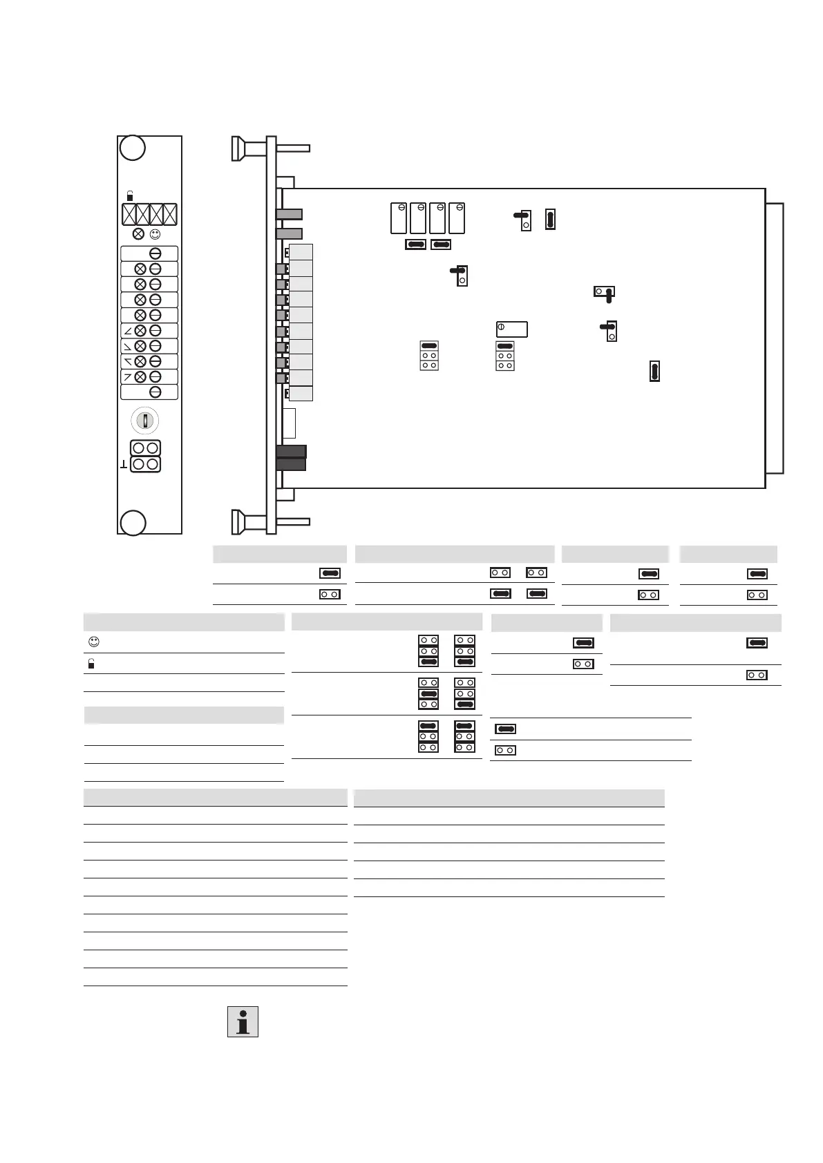
5.2.3 Setting and display elements of the amplifier card VT-VSPA../T5
The warranty expires if the sealed potentiometer is adjusted.
LED displays
Ready for operation (green)
Enable (yellow)
–1 External inverting
Measuring sockets
I, w, t Ready for operation (green)
⊥ Enable (yellow)
–1 External inverting
Potentiometer adjustable on the board
Gw+ Amplitude attenuator for positive command values
Gw– Amplitude attenuator for negative command values
S+ Step level for positive direction
S– Step level for negative direction
f Clock frequency output stage
Potentiometer (some of which with LED display)
zw Zero point calibration
w1 Command value 1
w2 Command value 2
w3 Command value 3
w4 Command value 4
t1 Ramp time 1
t2 Ramp time 2
t3 Ramp time 3
t4 Ramp time 4
t5 Ramp time 5
J3 ramp time
0.2 to 50 sec.
0.02 to 5 sec. •
J4 step function
Off
On •
J1 inverting
Off
On •
J8, J9 step level J8 J9
4WRA6 and 10...2X
4WRZ...7X, 3DREP...2X
J5, J6 clock frequency
J5 J6
4WRA6...2X
4WRA10...2X
Universal, 4WRZ...7X
3DREP...2X
J2 ramp function
Off
On •
J7 maximum current setting
4WRZ...7X •
3DREP...2X
4WRA...2X
• = factory setting of the jumpers
= jumper closed
= jumper open
 Loading...


