20/40 Information on this product
Bosch Rexroth AG, VT-VSPA2-1-2X/V0/T., RE 30110-B/11.2012
– 5 different ramp times can be set and enabled (see chapter "Ramp time selec-
tionlogic").
– The ramp times can be set using the potentiometers "t1" to "t5" and they can be
read and checked by means of the test socket "v".
• The following applies to the amplifier card VT-VSPA2../T1:
– Only one ramp time can be set. This time is the same for all command value modi-
fications (increase, decrease, positive and negative).
– The ramp time can be set using the potentiometer "t" and read and checked on
the measuring socket "t" (selection via measuring point selector switch).
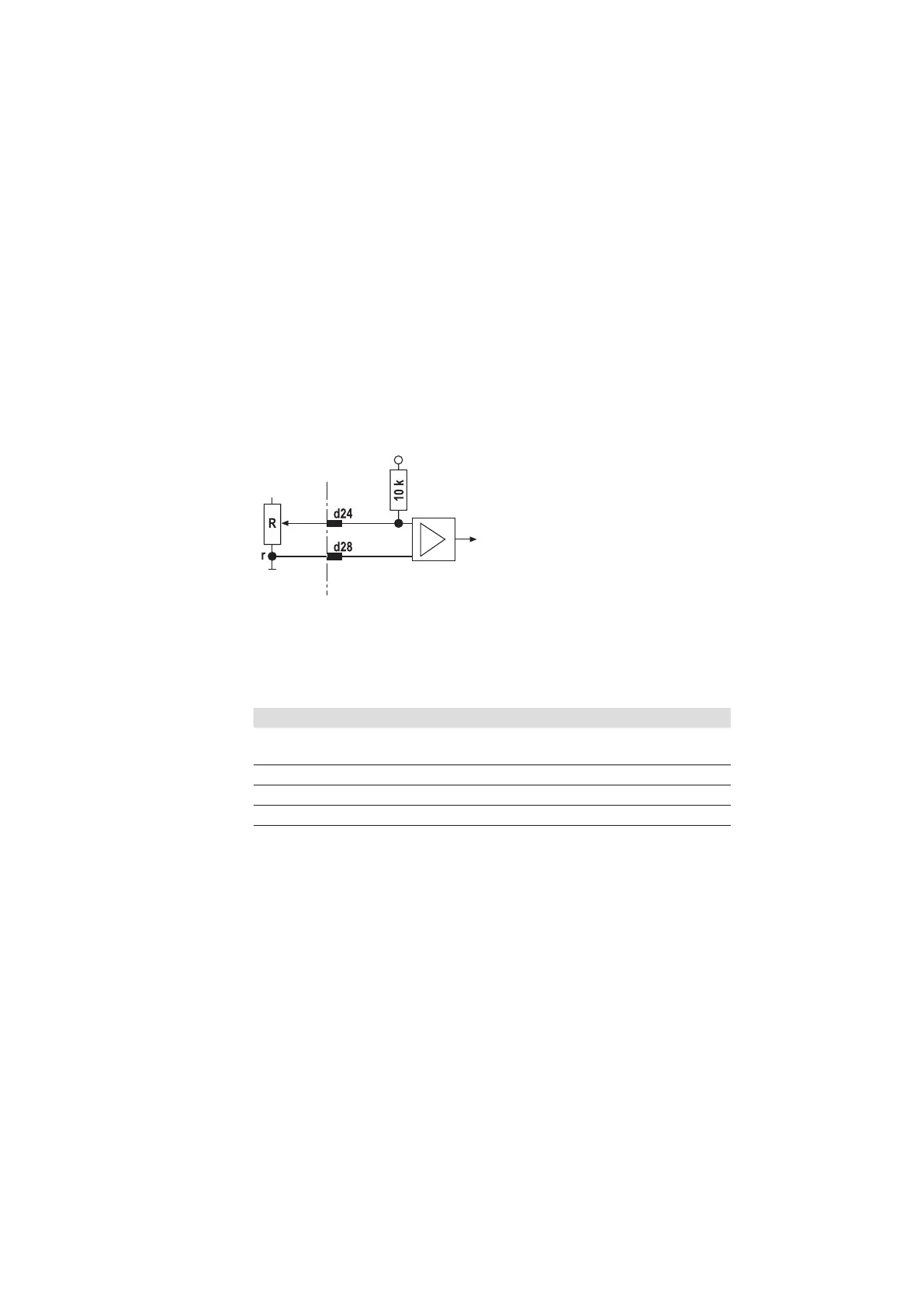
Using an external potentiometer the internally set ramp time can be extended. The
setting can be verified by means of the measuring socket. In case of a cable break,
the internal default setting will be valid automatically.
+15 V
+10 V
Fig. 4: Ramp time setting via external potentiometer
The setting range is dependent on the resistance "R".
Table 6: Ramp time setting
R Setting range
1)
Minimum ramp time potentiometer
angle of rotation = left turn
Maximum ramp time potenti-
ometer angle of rotation = 95%
1 kΩ
80 msec 1 sec
500 Ω
150 msec 2 sec
100 Ω
0.8 sec 10 sec
2)
The minimum ramp time can only be reached if the internally set ramp time is lower, i.e. the cor-
responding potentiometer is at the left stop.
The specified ramp times are true for jumper "J3" = open.
5.2.5 Ramp on/off
The ramp time can be set to a minimum (< 2 msec) via an external signal or a jump-
er(J2) (= ramp off). This is true irrespective of the specified ramp times.
If both measures are set simultaneously, they cancel each other out.
If the jumper (J2) is plugged, the 24V input functions as ramp "on" input.
If the ramp is active, this is indicated by an LED "T".
External ramp time setting
 Loading...


