Information on this product 19/40
RE 30110-B/11.2012, VT-VSPA2-1-2X/V0/T., Bosch Rexroth AG
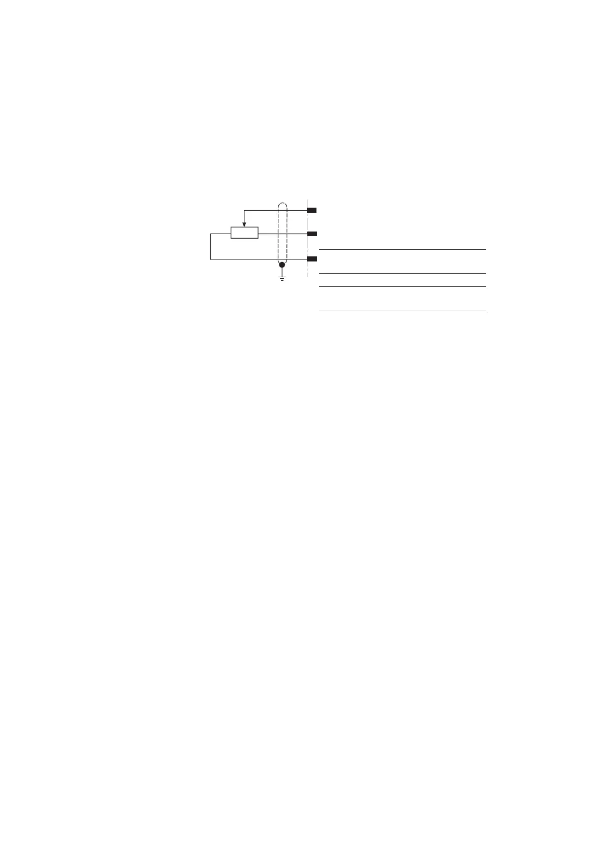
5.2.4.3 External command value voltages
The external command value voltages are either defined directly by regulated volt-
ages (+10V, –10 V; connection b30, b32) or via external potentiometers:
• If these command value inputs are directly connected to the regulated voltages, the
command values are set at the potentiometers "w1" to "w4".
• If you are using external potentiometers, the internal potentiometers will function
as attenuators or limiters.
b2, b4, b6 or b8
b32
(+10 V)
b30
(–10 V)
b32
(+10 V)
b28
(0 V)
b28
(0 V)
b30
(–10 V)
Command value range
0 to
+100 %
0 to
–100 %
–100 %
to +100 %
5 KΩ < R < 20 kΩ
Fig. 3: Command value setting via external potentiometer
5.2.4.4 Command value inversion [7]
The command value created internally from the input signals, the command value
call-ups and the zero point offset signal can be inverted by an external signal or
jumper J1. The inversion is displayed by an LED ("–1") on the front plate.
5.2.4.5 Enable function [8]
The enable function enables the power output stage and forwards the internal com-
mand value signal to the ramp generator. The enable signal is displayed by an LED on
the front plate. If enable is connected, the internal command value is changed (with
any kind of command value specification) by the set ramp time. Thus, a controlled
valve does not open abruptly.
5.2.4.6 Ram generator [9]
The ramp generator limits the rise of the input signal. A ramp-shaped output signal
develops from a specified step signal. The ramp time relates to a command value
modification of the input signal of 100%.
The ramp time is not increased or shortened in the downstream characteristic
curvegenerator.
Using the ramp "on/off" signal or the jumper J2 the ramp time is set to a minimum
(<2ms) (ramp off).
You can use jumper "J3" to select the possible setting range of the ramp time:
0.02- 5 sec. or 0.2 - 50 sec.
• The following applies to the amplifier card VT-VSPA2.../T5:
Adjustment options
 Loading...


