Hydraulics Bosch Rexroth AGRE 30110-Z/10.12 Additional information
5/10
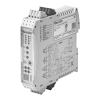
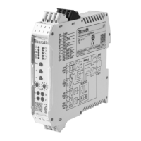
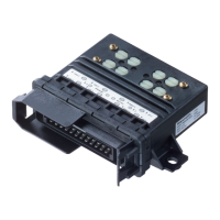
Block diagram / pinout VT 3006, VT 3017, VT 3018
i
u
u
K5
10c
10a
8a
12a
12c
K1.1
K2.1
K3.1
K4.1
R4
R3
R2
R1
+
K6
H1
H2
K3
K2
K1
H4
H3
K4
K5
K6
16a
26c
20c
2a
18a
16c
6c
6a
4a
8c
4c
18c
30a
24a
22a
28a
32a
+U
B
26a
J5, J6
u
2,5 A T
20a
I
B
32c
X1
0 V
28c
10
I
A
w
8
7
7
7
6
5
43
2
S
1
=
14c
14a
+9 V
M0
9 V
9
H12
H11
F F F F
1
S
F
F
F
F
F
X1
S
S
7
i
u
F
F
F
F
K1.2
K2.2
K3.2
K4.2
t4
F
t3
F
t2
F
t1
F
t5
F
H1 to H4
Display of the command value call-ups
H11 "power on"
H12 "Ready for operation"
Ramp external
Positive command value
controls solenoid "B".
Negative command value
controls solenoid "A".
1 Command values
2 Differential input
3; 6 Summing device
4 Ramp generator
5 Step function generator
7 Power output stage
8 Clock generator
9 Monitoring
10 Power supply
K1 to K6 Call-up relay
R1 to R4 Command values
t1 to t5 Ramp time
Command value 5 ±6 V
Command value 4 ±9 V
Command value 3 ±9 V
Command value 2 ±9 V
Command value 1 ±9 V
Differential input
Command value 6
Reference potential
Auxiliary voltage ±9 V
Measurement null (M0) is increased by 9
V as compared to the operating voltage!
Call-up command value 1
Call-up command value 2
Call-up command value 3
Call-up command value 4
Call-up "Ramp off"
Call-up "Switch-over auxiliary voltage"
Relay call-up voltage (+24 V)
Current command value at "w"
0 to +6 V for solenoid "A"
0 to –6 V for solenoid "B"
Actual current value I
A
at "I
A
"
Actual current value I
B
at "I
B
"
Bias current
Solenoid "A"
Solenoid
"A"
Solenoid "B"
Command value
after ramp
Bias current
Solenoid "B"
F = On front plate
Operating voltage

 Loading...

