F 002 DG9 H10 2018-08-21| Bosch Automotive Service Solutions GmbH
Repair | RG8.0 / RG4.0 | 13
en
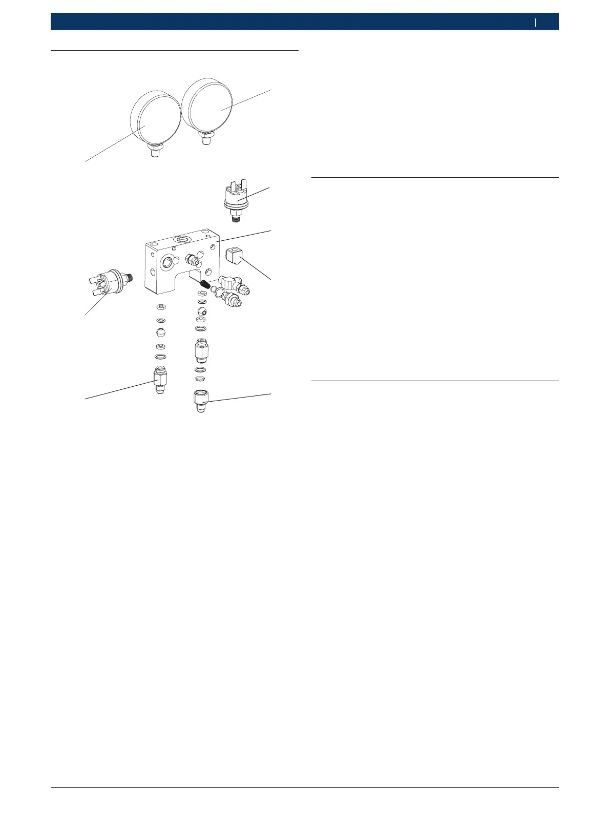
6.4 Replacing the manifold assembly
H00_15Nkv
1
2
4
6
7
8
Fig. 5: Overview of manifold assembly
1 LP gauge
2 LP pressure switch
3 Manifold block
4 Elbow connector
5 Inlet port
6 Outlet port
7 HP pressure switch
8 HP gauge
1. Execute the steps listed in chapter 3.1.
2. Disconnect the red, blue and black knobs on the
front panel.
3. Open the LH and RH enclosures.
4. Disconnect the electrical connections to LP and HP
pressure switches (Fig. 5, Pos. 2, 7).
5. Disconnect the earthing connection to the manifold.
6. Disconnect the copper tubings to the manifold.
7. Disconnect the inlet and outlet ports
(Fig. 5, Pos. 5, 6) from the manifold.
8. Unfasten the manifold mounting screws from the
front panel.
The manifold assembly is disconnected.
9. Assemble the new manifold assembly to the front
panel.
10. Fasten the red, blue and black knobs on the front
panel. Refer to section 3.3 for the knob positions.
11. Connect the inlet and outlet ports to the manifold.
12. Connect the copper tubings back to the manifold.
13. Restore the electrical connection to the HP and LP
pressure switches.
14. Restore the earthing connection to the manifold.
15. Close the LH and RH enclosures.
16. Perform the basic operational test as outlined in
chapter 5.1.
"If the basic operational test passes, you have suc-
cessfully replaced the manifold assembly.
6.5 Replacing the HP gauge
1. Execute steps 1 to 8 listed in chapter 6.4.
2. Grip the manifold assembly in a bench vise.
3. Loosen and remove the HP gauge from the manifold.
4. Clean the threaded portion of the manifold where
the HP gauge is assembled.
5. Apply Loctite 577 to the threads of the HP gauge.
6. Assemble the new HP gauge to the manifold.
7. Dismount the manifold assembly from the bench
vise.
8. Execute steps 10 to 15 of chapter 6.4.
9. Perform the basic operational test as outlined in
chapter 5.1.
"If the basic operational test passes, you have suc-
cessfully replaced the HP gauge.
6.6 Replacing the LP gauge
1. Execute steps 1 to 8 listed in chapter 6.4.
2. Grip the manifold assembly in a bench vise.
3. Set the temperature in the range of 50
o
C to 80
o
C
(depending on the ambient temperature) on a heat
gun. Direct the heat gun off of the elbow connector
(Fig. 5, Pos. 4) at a distance of 3 cm to 4 cm.
4. Heat the elbow connector for three to four minutes.
5. Hold the elbow connector using a suitable tool and
disconnect the LP switch.
6. Loosen and remove the LP gauge from the manifold.
7. Clean the threaded portion of the manifold where
the LP gauge is assembled.
8. Apply Loctite 577 to the threads of the LP gauge.
9. Assemble the new LP gauge to the manifold.
10. Clean the threaded portion of the elbow connector.
11. Apply fresh Loctite 577 to the threads of the elbow
connector.
12. Fasten the LP switch to the manifold.
13. Dismount the manifold assembly from the bench
vise.
14. Execute steps 10 to 15 of chapter 6.4.
15. Perform the basic operational test as outlined in
chapter 5.1.
"If the basic operational test passes, you have suc-
cessfully replaced the LP gauge.

 Loading...