EasyManuals Logo

Bosch RG8.0 Repair Instructions

Bosch RG8.0
36 pages
To Next Page IconTo Next Page
To Previous Page IconTo Previous Page
Page #19 background imageLoading...
Page #19 background image
F 002 DG9 H10 2018-08-21| Bosch Automotive Service Solutions GmbH
Electrical terminal diagram | RG8.0 / RG4.0 | 19
en
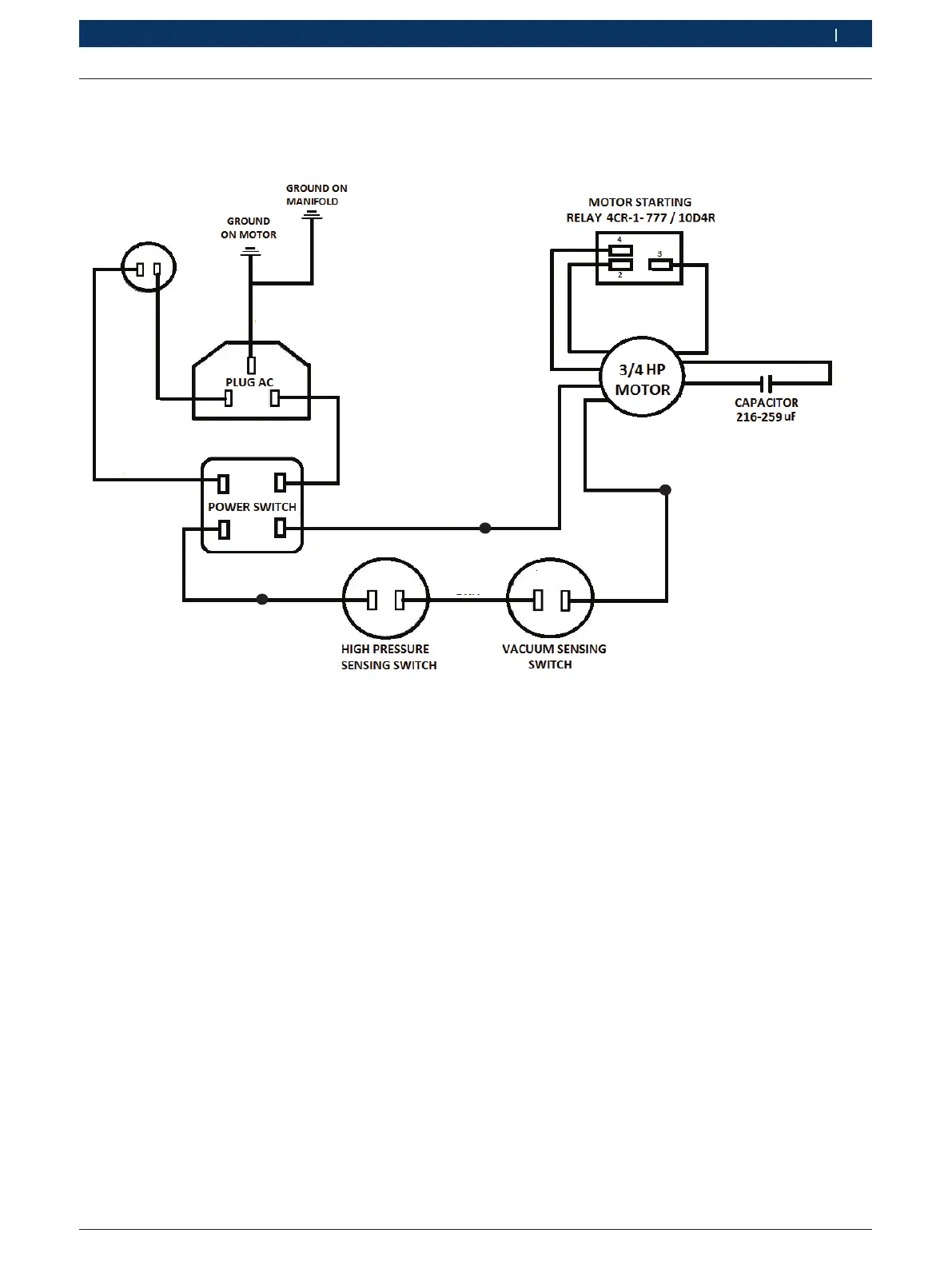
7.2 For RG8.0, 110 V, 60 Hz variant
H00_17Nkv
F2
F1
L
N
UT1
VT2
RL1
J1 J1
SL2
HP1
HP2
YLW
LP1
LP2
BLU
Brown
Yellow
Blue color
with female
flag connector
Blue with male
connector
CIRCUIT BREAKER (15 A)
Red
Black
Fig. 9: Electrical terminal diagram for RG8.0, 110 V, 60 Hz variant

Table of Contents

Other manuals for Bosch RG8.0

Questions and Answers:

Question and Answer IconNeed help?

Do you have a question about the Bosch RG8.0 and is the answer not in the manual?

Bosch RG8.0 Specifications

General IconGeneral
BrandBosch
ModelRG8.0
CategoryTest Equipment
LanguageEnglish

Related product manuals