F 002 DG9 H10 2018-08-21| Bosch Automotive Service Solutions GmbH
14 | RG8.0 / RG4.0 | Repairen
6.7 Replacing the HP switch
1. Execute steps 1 to 8 listed in chapter 6.4.
2. Grip the manifold assembly in a bench vise.
3. Loosen the HP switch from the manifold.
4. Clean the threads of the manifold after disconnect-
ing the HP switch.
5. Apply Loctite 577 to the threads of the new HP
switch. Fasten the new HP switch to the manifold.
6. Execute steps 10 to 15 listed in chapter 6.4.
7. Perform the basic operational test as outlined in
chapter 5.1.
"If the basic operational test passes, you have suc-
cessfully replaced the HP switch.
6.8 Replacing the LP switch
1. Execute steps 1 to 8 listed in chapter 6.4.
2. Grip the manifold assembly in a bench vise.
3. Set the temperature in the range of 50
o
C to 80
o
C
(depending on the ambient temperature) on a heat
gun. Direct the heat gun off of the elbow connector
(Fig. 5, Pos. 4) at a distance of 3 cm to 4 cm.
4. Heat the elbow joint for three to four minutes.
5. Loosen the LP switch from the elbow joint.
6. Clean the threaded portion of the elbow joint.
7. Apply Loctite 577 to the threads of the new LP
switch.
8. Assemble the new LP switch to the elbow connector.
9. Execute steps 10 to 15 listed in chapter 6.4.
10. Perform the basic operational test as outlined in
chapter 5.1.
"If the basic operational test passes, you have suc-
cessfully replaced the LP switch.
6.9 Replacing the condenser
1. Execute the steps listed in chapter 3.1.
2. Open the LH and RH enclosures.
3. Unfasten the copper tubing (Fig. 3, Pos. 5, 23) /
(Fig. 4, Pos. 1, 20) from the manifold to the con-
denser.
4. Unfasten the mounting screws of the condenser
(Fig. 3, Pos. 10) / (Fig. 4, Pos. 18) from the bottom
panel of the RG8.0 / RG4.0.
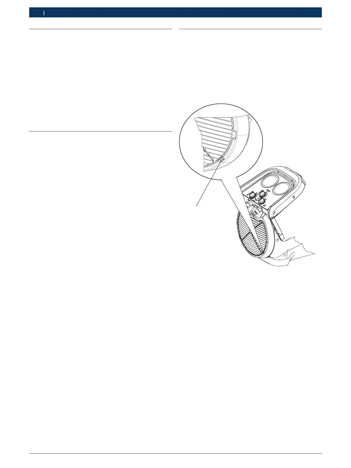
1
Fig. 6: Opening the front grill
1 Lock on front grill
5. Press the locks (Fig. 6, Pos, 1) of the front grill and
release the front grill.
6. Unfasten the screws of the condenser behind the
front grill.
7. Remove the condenser from the mounting position.
8. Fasten the new condenser to the bottom panel of
the RG8.0 / RG4.0.
9. Fasten the screws behind the front grill.
10. Fasten the copper tubing from the manifold to the
condenser.
11. Close the front grill.
12. Close the LH and RH enclosures.
13. Perform the basic operational test as outlined in
chapter 5.1.
"If the basic operational test passes, you have suc-
cessfully replaced the condenser.

 Loading...