F 002 DG9 H10 2018-08-21| Bosch Automotive Service Solutions GmbH
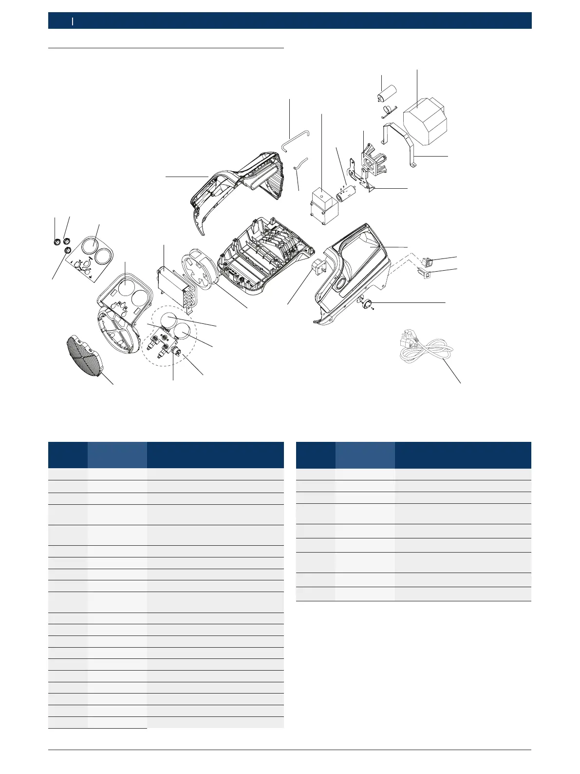
8 | RG8.0 / RG4.0 | Overview of partsen
4.2 Parts list - RG4.0
1
10
2
3
5
6
7
12
11
B
A
D
C
9
14
15
16
17
19
20
18
8
21
22
23
24
25
Fig. 4: Exploded view of RG4.0
Position
number
Part number Part description
1 RGB400100 Tube - Manifold to compressor inlet
2 RGB400120 Compressor
3 RGB400130 Start capacitor (only for 115 V)
4 RGB400150
RGB400140
Motor 230 V
Motor 115 V
5 RGB400290
RGB400160
Motor bracket 230 V
Motor bracket 115 V
6 RGB400280 LH enclosure
7 RGB480120 Knob - Main power switch
8 RGB480130 Pump bracket
9 RGB480140 Main power switch
10 RGB400180
RGB400170
Electrical fan 230 V
Electrical fan 115 V
11 RGB480150 Manifold assembly
A RGB480160 Gauge - High pressure
B RGB480170 Gauge - Low pressure
C RGB480180 Switch - High pressure
D RGB480190 Switch - Low pressure
12 RGB400190 Grill - gray
13 RGB480200 Knob - Ball valve (Red)
14 RGB480210 Knob - Ball valve (Blue)
15 RGB480220 Knob - Ball valve (Black)
16 RGB480230 HMI cover
Position
number
Part number Part description
17 RGB480240 Front Panel
18 RGB480250 Condenser
19 RGB480260 RH Enclosure
20 RGB400200 Tube- Manifold to compressor
outlet
21 RGB400210 Interface - Motor and compressor
22 RGB400220 Coupler
23 RGB480310
RGB400300
Circuit breaker 8 A, 230 V
Circuit breaker 12 A, 115 V
24 RGB480320 Power receptacle, 230 V / 115 V
25 RGB480330 Power cord, 230 V

 Loading...