EasyManuals Logo

Bosch RG8.0 Repair Instructions

Bosch RG8.0
36 pages
To Next Page IconTo Next Page
To Previous Page IconTo Previous Page
Page #21 background imageLoading...
Page #21 background image
F 002 DG9 H10 2018-08-21| Bosch Automotive Service Solutions GmbH
Electrical terminal diagram | RG8.0 / RG4.0 | 21
en
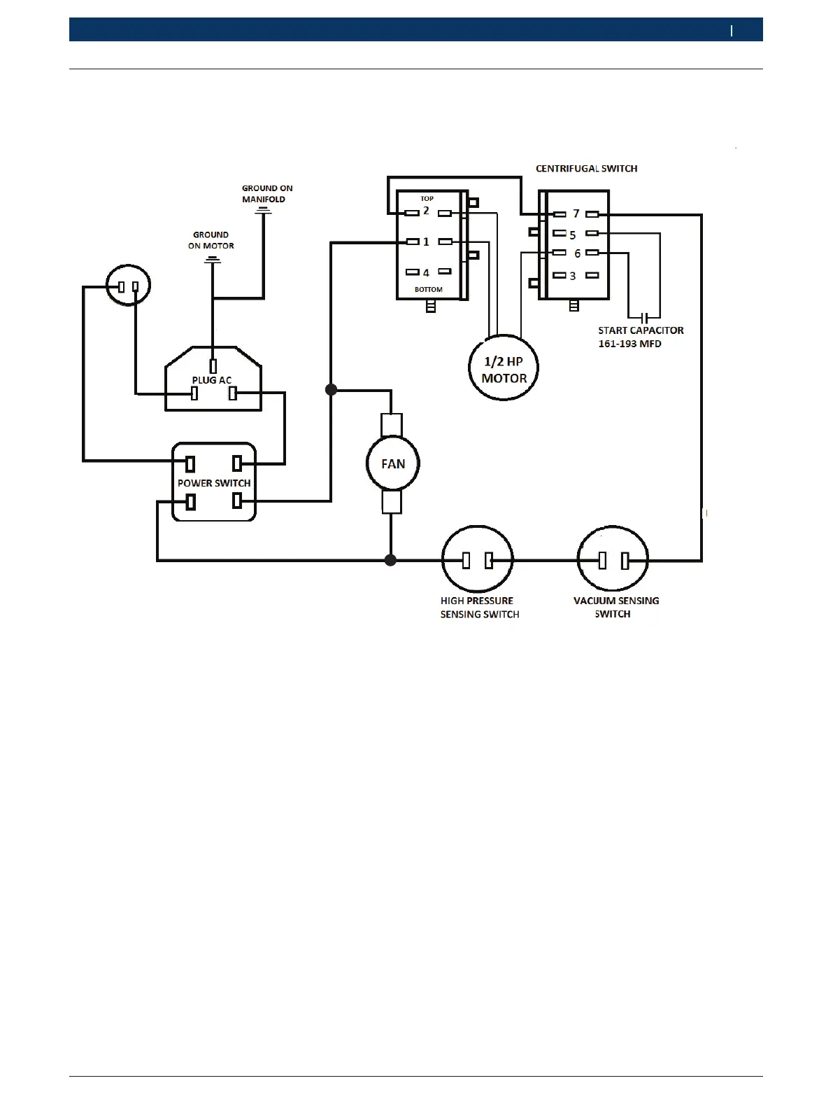
7.4 For RG4.0, 110 V, 60 Hz variant
H00_22Nkv
F2 F1
L N
77
5
6
UT1 VT2
SL2
Pink
J2
J2
J1 J1
RL1
HP1 HP2
LP1 LP2
2
1
CB CA
CIRCUIT BREAKER (12A)
Black
Blue
Fig. 11: Electrical terminal diagram for RG4.0, 110 V, 60 Hz variant

Table of Contents

Other manuals for Bosch RG8.0

Questions and Answers:

Question and Answer IconNeed help?

Do you have a question about the Bosch RG8.0 and is the answer not in the manual?

Bosch RG8.0 Specifications

General IconGeneral
BrandBosch
ModelRG8.0
CategoryTest Equipment
LanguageEnglish

Related product manuals