F 002 DG9 H10 2018-08-21| Bosch Automotive Service Solutions GmbH
6 | RG8.0 / RG4.0 | Requirements for repair en
3. Requirements for repair
R Personal Protective Equipment (PPE)
R Heat gun for unfastening joints secured by Loctite
R General tools for electricians and A/C mechanics
R Loctite 577 for fastening hydraulic joints
R Cleaning medium for hydraulic joints
R Dry powder for dousing fire or CO
2
fire extinguisher,
if the RG8.0 / RG4.0 is used to recover flammable
refrigerants.
3.1 Preparations for repair
! Do not perform repair without executing the steps
listed in this chapter.
1. Ensure that the knob positions are set as follows:
$ Black knob to RECOVER position
$ Red and blue knobs to CLOSED position
2. Observe the pressure gauges. Ensure that the read-
ing is 0. Else purge the residual refrigerant in the
RG8.0 / RG4.0 (refer chapter 3.2).
If the purging is successful, the reading on the
pressure gauges should be 0. Else, replace the
pressure gauges (refer chapter 6.5).
3. Switch off the mains supply to the RG8.0 / RG4.0.
4. Disconnect the power cable from the mains supply.
5. Disconnect the other end of the power cable from
the power socket of the RG8.0 / RG4.0.
3.2 Purging residual refrigerant
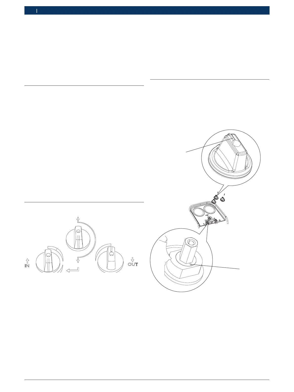
LIQUID
VAPOUR
OPEN
PURGE
CLOSED
CLOSED
Fig. 1: Valve positions for purging residual refrigerant
1. Ensure that the inlet control valve of the
RG8.0 / RG4.0 is in the CLOSED position.
2. Ensure that the outlet control valve is open and con-
nected to a recovery tank with the same refrigerant
as in the unit.
3. Ensure that the RG8.0 / RG4.0 is powered off.
4. Turn the recovery / purge (Black) knob of
RG8.0 / RG4.0 to PURGE position (pointed down-
wards) as shown in Fig. 1
5. Start the RG8.0 / RG4.0 and slowly turn the inlet
(Blue) control valve of the RG8.0 / RG4.0 to PURGE
position as shown in Fig. 1.
The RG8.0 / RG4.0 starts purging automatically.
6. Run until desired vacuum is achieved or until low
pressure switch shuts off the RG8.0 / RG4.0.
7. Close the valve on the recovery tank, then the outlet
control valve of the RG8.0 / RG4.0.
8. Power off the RG8.0 / RG4.0.
9. Turn the inlet control valve to the closed position.
10. Close all hose shut-off valves, then disconnect and
store the hoses.
3.3 Instructions for replacement of red,
blue and black knobs
Follow these instructions when you remove the red,
blue and black knobs during repair. Only one of the
knobs and the corresponding valve is depicted in the
following illustration. The instructions are applicable for
all the knobs.
1
2
H00_35Nkv
Fig. 2: Overview of knob and ball valve
1 Direction indicator
2 Indent on ball valve
1. Before fixing the knob to the ball valve, notice the
indent on the ball valve (Fig. 2, Pos. 2).
2. Fix the knob such that the direction indicator
(Fig. 2, Pos. 1) of the knob is latitudinally opposite
to the indent.

 Loading...