57
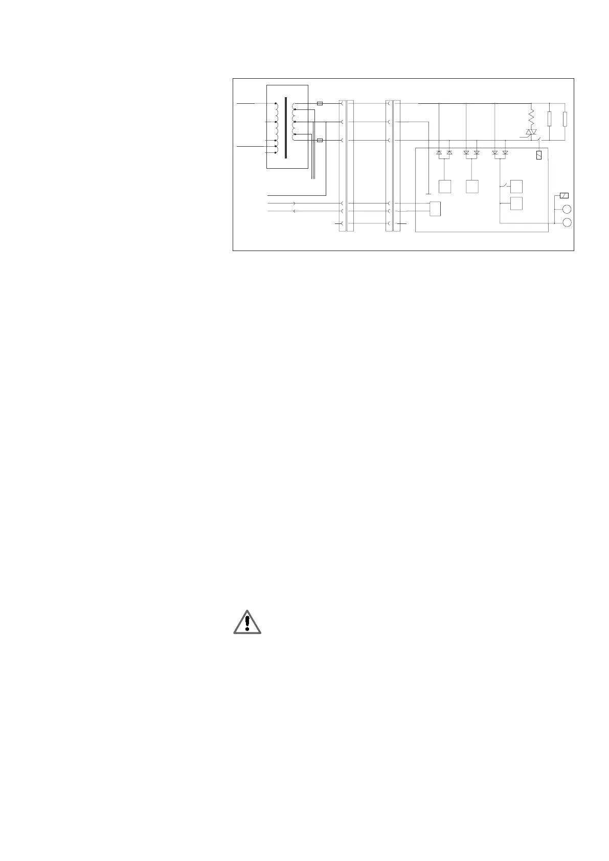
5.3.2 Circuit diagram
5.4 Exchanging the mother-
board/processor board
M
M
230V
110V
0V
-15V
+15V
8 AT
8 AT
10V
10V
14.5V
14.5V
Chamber
heater
100W
28V
1 688 400 048
-9V +9V +12V
+5V
analog analog
EEPROM
Processor
TxD
RxD
Gnd
6,7,8
4,5
10,11,1
TxD
RxD
2
3
1
Shield
1,2,3
4,5
7,8,9
10
11
12
AMP, 16 pinSubD, 15 pin
1,2,3
4,5
7,8,9
10
11
12
6,7,8
4,5
10,11,1
2
3
1
5
4
3
2
1
MTM
K1
RS 232
459601/3CK
– Unplug the connection lead connecting the RTM 430 to the emission system analyzer
or emission analysis module.
– Place the RTM 430 (on a clean surface) on its back.
– Remove the cover caps on the left and right-hand sides of the RTM 430 (Figure 2,
Item 1).
– Unscrew the two countersunk-head screws on the rear side of the unit.
– Unscrew the four securing screws on the underside of the unit (Figure 2, Item 2).
– Carefully pull the housing cover to the rear and place it down (the ventilators are simply
slid into a guide and are not screwed in place).
– Remove the four securing nuts of the PCB cover using a size 7 socket wrench (Figure
2, Item 3).
! The RTM must have been disconnected from the electrical power supply in order to
prevent the risk of short circuit between PCB cover and Triac.
– Turn the PCB cover so that the opening points upwards.
– Remove the rubber grommet from the PCB cover (Figure 2, Item 4).
– Carefully cut open and remove the cable ties (Figure 2, Item 5).
– Unplug all leads on the PC board and, when doing this, carefully detach the connection
leads to the coaxial cables on emitter and receiver using a pair of flat-nosed pliers.
– Remove defective PC board.
– Plug all leads onto the new PC board (Figure 2).
– Insert the rubber grommet at the opening provided in the PCB cover (Figure 2,
Item 4).
– Secure the PCB cover to the threaded bolts using the four securing nuts (Figure 2, Item
3) using a size 7 socket wrench.
The PE wire must be connected as prescribed.
– Check the installation position of the ventilators. If necessary, slide the ventilators into
the guide rails (Figure 2, Item 9).
– Attach the housing cover.
– Connect the RTM 430 to the service PC and power supply unit (or emission
analysis module) using the interconnecting cable 1 684 463 389.
– Carry out a function check of the RTM 430 with the “Test functions” menu
(Chapter 6.3).
– If necessary, set the RTM 430 to the country-specific parameters in the “Read and
set service-parameters” and “Service-program settings” menu (Chapters 6.2
and 6.8).