Precision™ Spinal Cord Stimulator System Clinician Manual
Clinician Manual
97035873-01 26 of 75
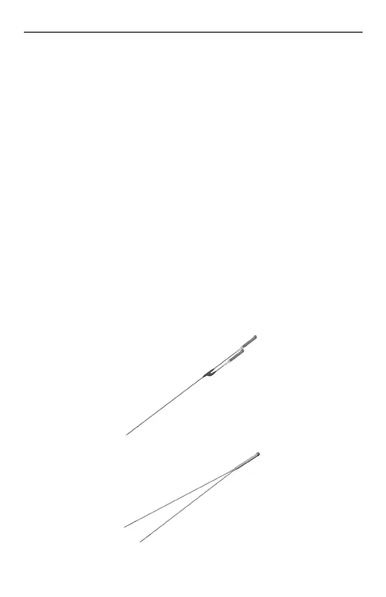
Lead Connection to Splitter
1. Carefully withdraw the stylets from the leads to be inserted into the splitter.
2. Wipe clean the proximal connector ends of the leads.
3. Select the desired splitter model.
Note: A Splitter 2x8 must be used when implanting the Innion™ 16 lead.
4. Check that the lead connector end can be easily inserted into the splitter without obstruction. If
obstruction is encountered, loosen the set screws of the splitter by using the hex wrench provided, turning
counterclockwise.
Note: • The set screw should only be loosened to an amount sufcient to insert a lead.
• Do not excessively loosen the set screw. This may cause the set screw to dislodge rendering the
splitter unusable.
5. Insert proximal connector ends of desired leads into splitter receptacles until they are fully seated – each
lead bottoms out in receptacles and retention sleeves (long ring) are under the setscrew blocks of the
splitter receptacles. Do not tighten set screw at this time.
6. Continue to “Connecting the OR Cable Assembly” on page 29, then proceed to step 7 below.
7. Check connections with an impedance measurement. If the impedance is satisfactory, proceed to
“Intraoperative Stimulation Testing” on page 30 to conrm proper lead location.
Note: Do not tighten set screw mechanical lock before intra-operative stimulation testing.
Note: On the 2x4 Splitter, the shorter splitter receptacle corresponds to contacts 1-4, while the longer
receptacle corresponds to contacts 5-8. Make note of which lead is connected to each splitter
receptacle.
Note: On the Splitter 2x8, one tail is laser-marked with bands, and corresponds to contacts 1-8 on the Innion
16 percutaneous lead; the unmarked tail corresponds to contacts 9-16.