11 Technical specifications
900-350_IFU_V2.6_10296-S13-20100111-EN ARC 300 / ARC 350 Operating manual 105
Setting Program
Micro Bipolar COAG 7, 8, 10
ARC350BMCOAG_SE_080125_1
0
10
20
30
40
50
60
10 100 1000 10000
P [W]
Bipolar Micro
COAG 25W
Bipolar Micro
COAG 50W
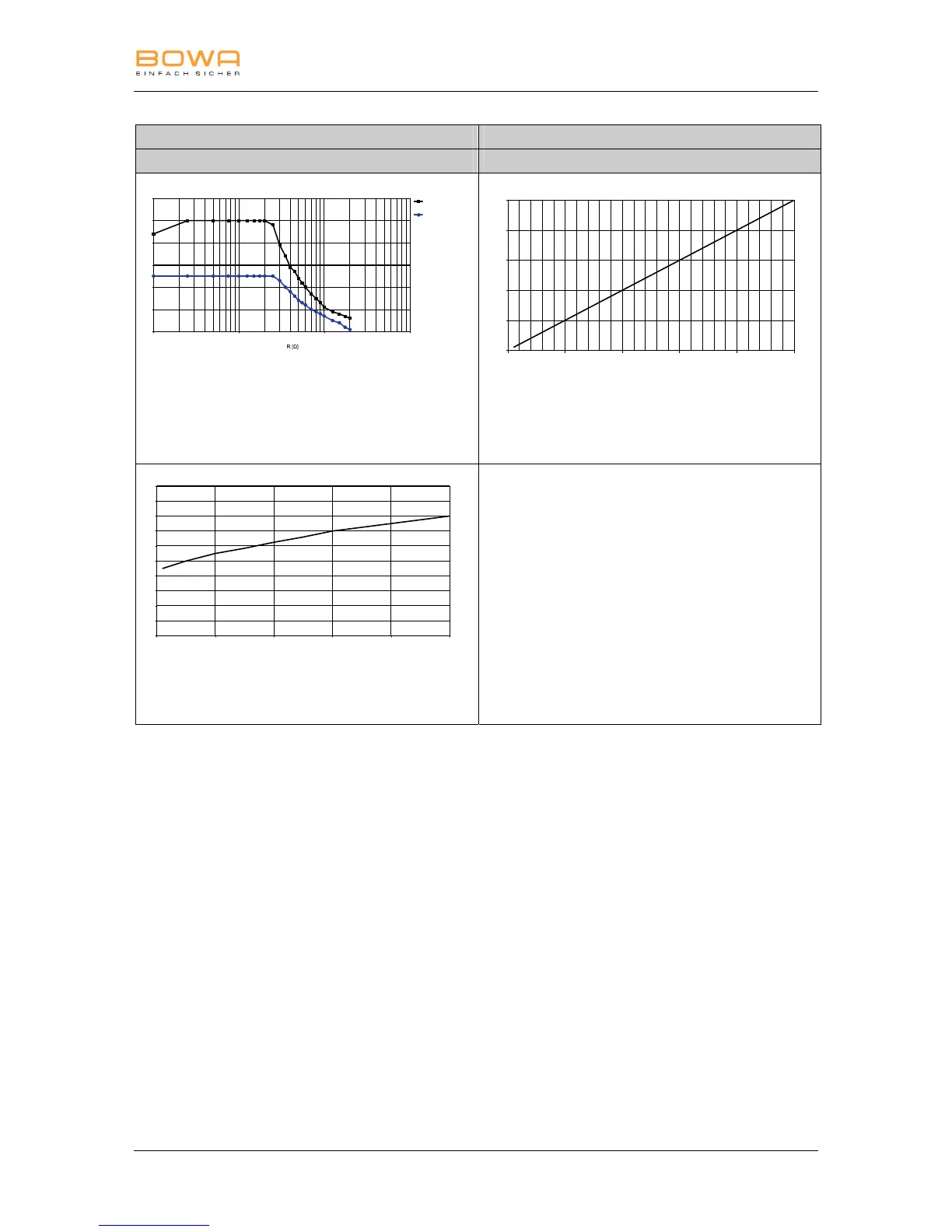
Measurement of resistances
• Diagram of power output P [W] as a
function of the load resistance R [Ω] for
the setting “Micro Bipolar COAG” =
50 W/25 W
ARC350BMCOAG_SE_080125_3
0
10
20
30
40
50
010
20 30 40 50
displayed value
P [W]
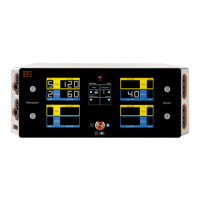
• Diagram of power output P [W] as a
function of the “Micro Bipolar COAG”
setting. Measured load resistance =
75 Ω
ARC350BMCOAG_SE_080125_2
0
01020304050
20
40
60
80
100
120
140
160
180
200
displayed value
U [Vp]
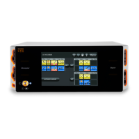
• Diagram of HF output voltage U [Vp] as
a function of the “Micro Bipolar COAG”
setting (idle mode)