Assembling Your BOWFLEX Ultimate
11
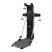
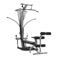
Step 9: RAIL END CAP INSTALLATION
Locate the following parts for this step:
• Rail End Cap
(Item #58)
• Two (2) #10X3/4" self tapping screw (Item #44)
❏ Place the end cap (Item #58) on the end of the rail with arrow
inside end cap facing up.
❏ Secure the end cap to the end of the rail using two (2)
#10X3/4" self tapping screws
(Item #44) shown in Figure H.
Figure H
58
Unit appears like
this following this
assembly step
Components for this
step are in Box 4
44
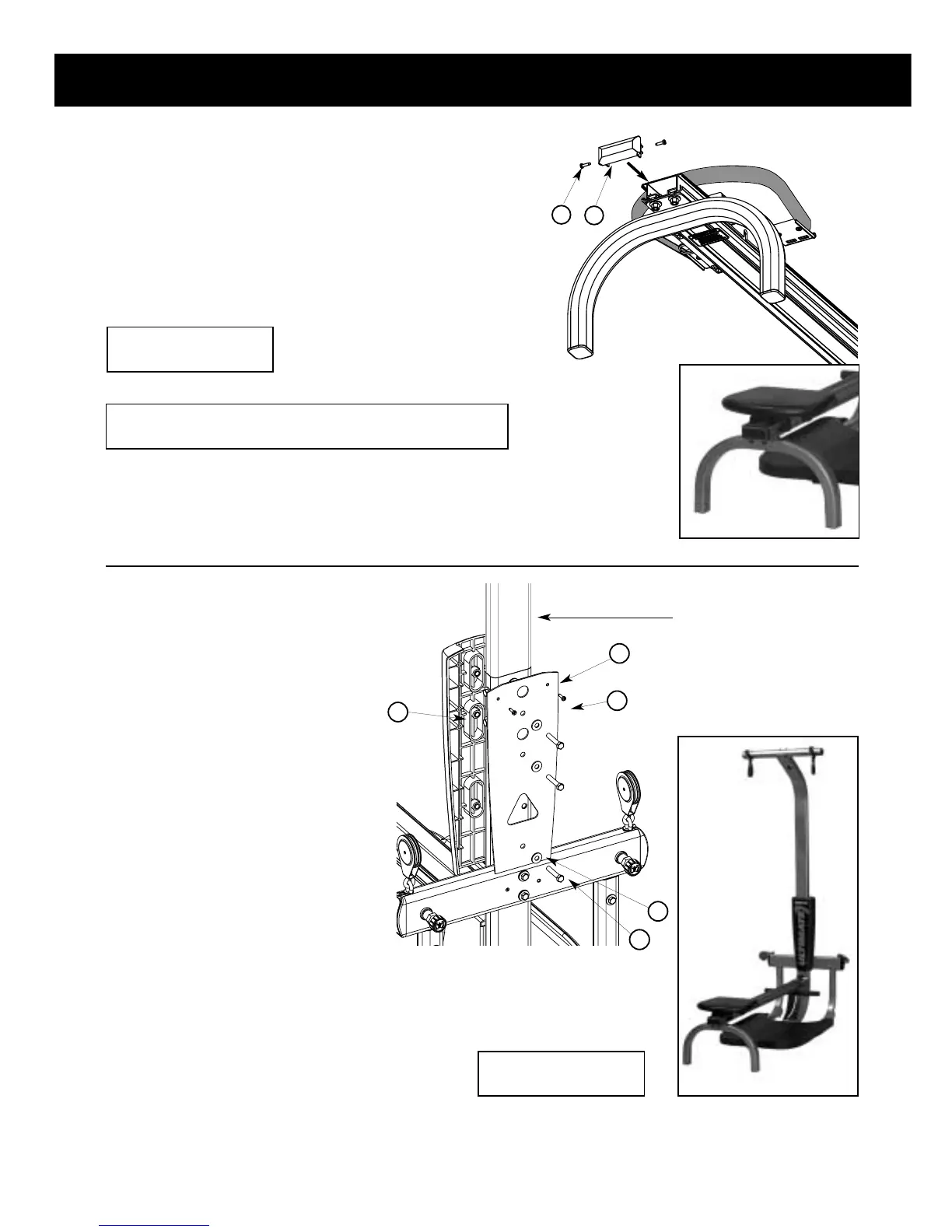
Step 10: INCLINE BENCH REST INSTALLATION
Locate the following parts for this step:
• Incline bench rest (Item #21)
• Incline bench rest back (Item #22)
• Three (3) 3/8"X2" bolts (Item #48)
• Three (3) 3/8" washers (Item #54)
• Two (2) #10X3/4" self tapping screws
(Item #44)
❏ Match up the oval bosses on the
incline seat rest
(Item #21) with the oval
cutouts in the lower lat tower
(Item #1)
as shown in Figure K.
❏ Place the incline bench rest back (Item
#22)
on the rear of the lower lat tower
(Item #1) and match up the three holes
for the 3/8" bolts as shown in Figure K.
Note: Make sure the textured, non-
machined side of the incline rest back
faces outward away from the machine.
❏ Slide the three (3) 3/8"X2" bolts (Item #48) into
the three holes in the incline bench rest back
(Item
#22)
through the lower lat tower (Item #1) and into
the incline seat rest (Item #21) as shown in Figure
K. Securely tighten these three bolts.
❏ Screw the two (2) #10X3/4" (Item #44) screws
into the incline bench rest back
(Item #22) as
shown in Figure K.
22
21
44
54
48
Figure K
Unit appears like
this following this
assembly step
(shown with
optional lat tower)
Components for this
step are in Box 4
If your unit came with a lat attachment, skip now
to lat instructions: Step 1 Page 14.
optional lat tower