Assembling Your BOWFLEX Ultimate
12
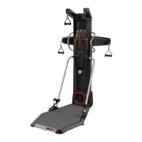
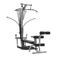
Figure L
Step 11: ROD BOX INSTALLATION
Locate the following parts for this step:
• Rod box with Power Rods
(Item #23)
• Rod box frame (Item #24)
• Three (3) #10X1" self tapping screw
(Item #45)
• Three (3) 1/4" washers (Item #55)
❏ Slide rod box with Power Rods (Item
#23)
into rod box frame (Item #24) as
shown in Figure L.
❏ Tighten three (3) #10X1" screws (Item
#45)
with three (3) 1/4" washers (Item
#55)
through the slot in rod box frame
(Item #24) and into the screw bosses in
the bottom of the rod box with Power
Rods
(Item #23) as shown in Figure L.
23
24
55
45
Step 12: ROD BOX FRAME INSTALLATION
Locate the following parts for this step:
• Rod Box with Power Rods with frame
(Items #23 & 24)
• Three (3) 3/8"X3/4" bolts (Item #46)
• Three (3) 3/8" washers (Item #54)
❏ Start two (2) 3/8"X3/4" bolts (Item #46) with 3/8" washers (Item
#54)
into the lower two holes in the rear of the lower lat tower
(Item #1) as shown in Figure M.
❏ Slide the rod box frame (Assembly #24) onto the two bolts
making sure the rod box frame is behind the washers as shown in
Figure M.
❏ Thread the third 3/8"X3/4" bolt (Item #46) into the top hole of
the rod box frame
(Item #24). Securely tighten all bolts.
54
46
Figure M
Unit appears like
this following this
assembly step
Unit appears like
this following this
assembly step
(shown with
optional lat
tower)
Components for this
step are in
Box 1 & Box 4
CAUTION:
When hooking up the Power Rods, do
not stand directly over the tops of the
rods. Stand off to the side while
connecting and disconnecting the
Power Rods from the cables.