Brady IP Series Printer
Replacing assembly units
Edition 12/07 Service Manual 15
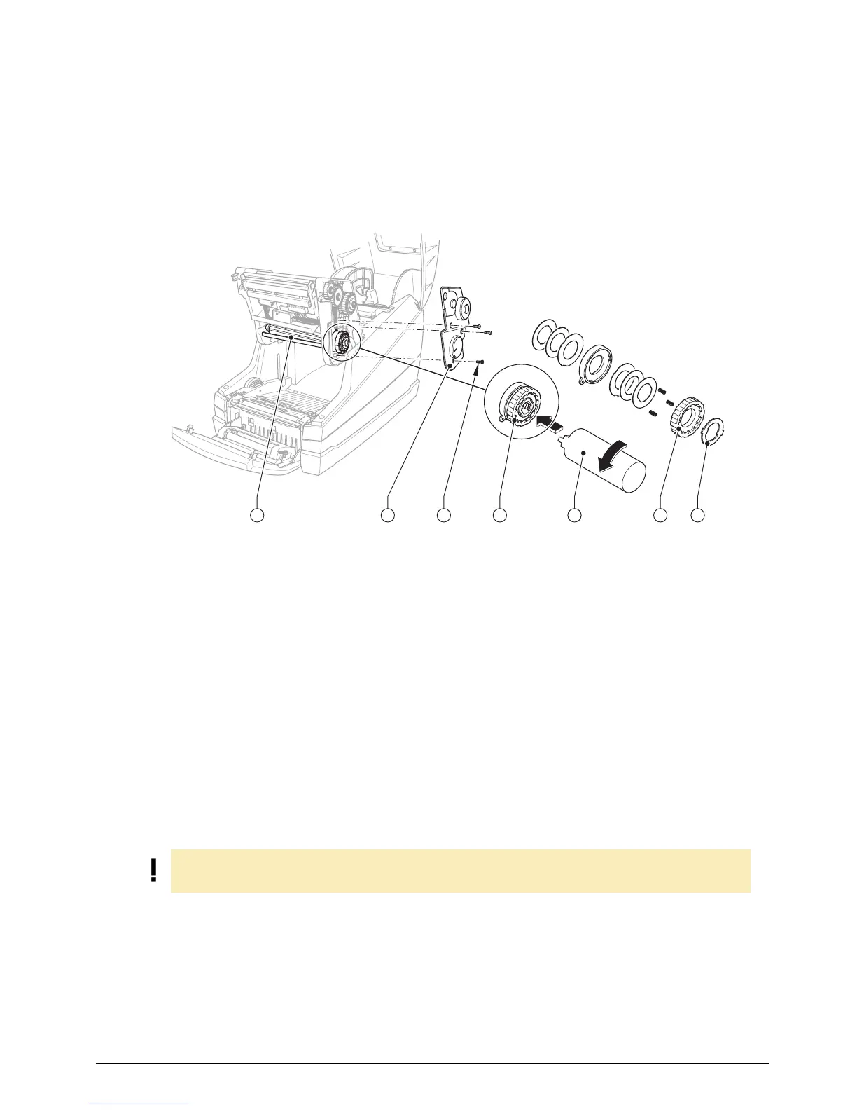
2.9 Replacing the brake of the ribbon supply hub
Fig. 8: Replacing the brake of the ribbon supply hub
1. Hinge up the printhead assembly, unscrew the three screws (3), and remove the cover (2).
2. For easier handling:
− Ensure that the tape holder (1) is attached.
− Press the holder (6) of the friction clutch inwards, turn it into the position 1 and release. Ensure
that the locking lugs have been fully inserted into the recesses of the knurled ring.
3. Grip the tape holder (1) that the axle cannot rotate, press the holder (6) of the friction clutch inwards
and turn the lock washer (7) using the tool (5) counterclockwise until it is released, then take it off.
4. Take off the several elements of the brake and mount the new parts in reverse order.
5. Grip the tape holder (1) that the axle cannot rotate, press the lock washer (7) in and turn it until it
clicks into place noticeable.
6. Turn the holder (6) back to it’s original position, measure the winding torque (see section 3.1) and
correct if necessary (see section 3.2).
7. Re-attach the cover (2) with the three screws (3).
1
Tape holder of the ribbon supply hub
2 Cover
3 Three screws
4 Brake
5 Clutch mounting tool
6 Holder
7 Lock washer
6
5
4
3
2
1
3
4
5
6
7
4
3
2
1
6
3
4
5
6
7
5
5
6
7
1
2
3
4
1
2
3
4
5
6
7
5
6
7
1
2
3
4
1
2
3
4
5
6
7
542 6 731
NOTE!
Ensure that the markings of the lock washer are outside.