20 Service Manual Edition 12/07
Replacing assembly units
Brady IP Series Printer
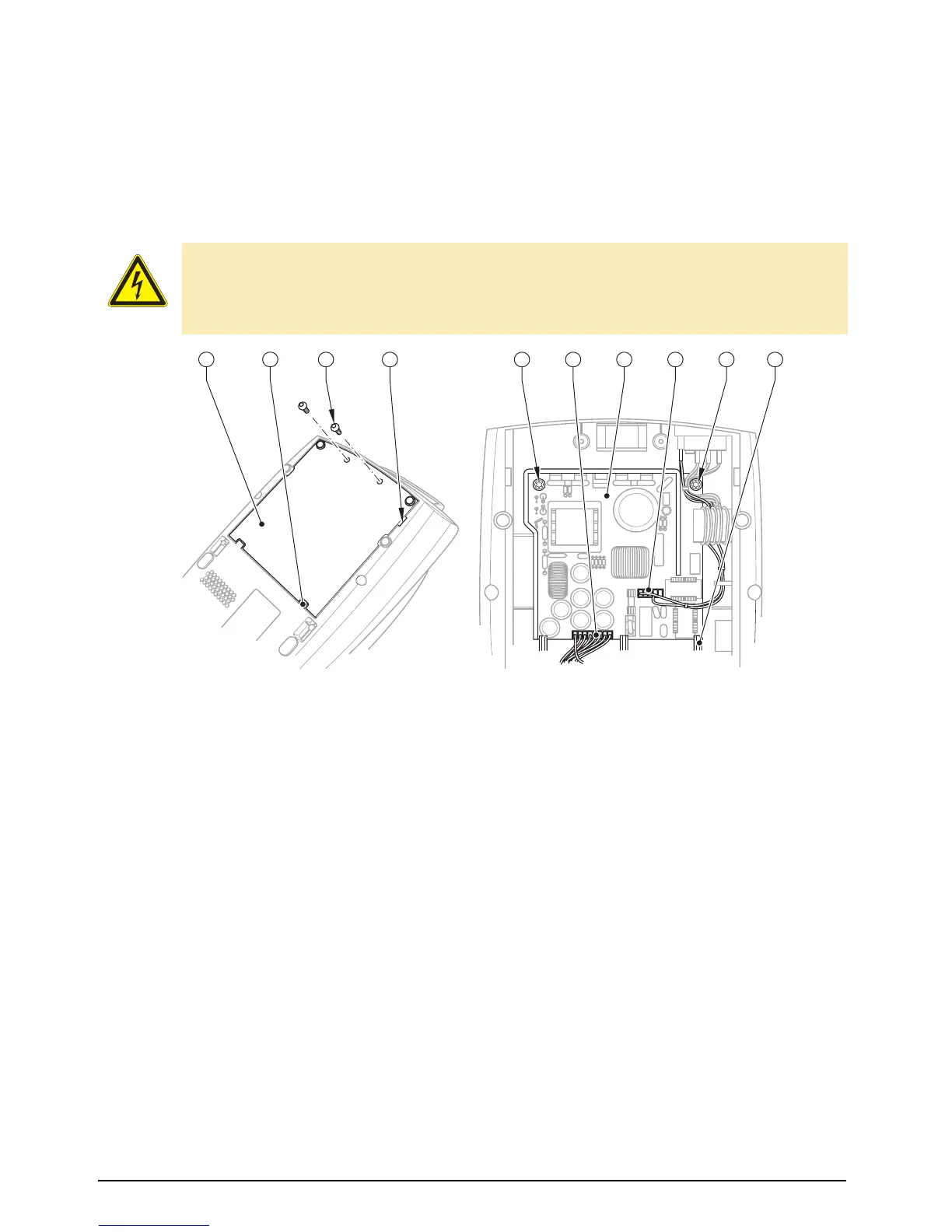
2.14 Replacing the power unit
Fig. 13: Replacing the power unit
1. Turn the printer and place it on a suitable underlay.
2. Loosen the two screws (3).
3. Insert a screwdriver into the recess (4), lift and remove the cover (1).
4. Unplug the mains input (9) and power unit (7) cables.
5. Remove two screws (5).
6. Remove the power unit (7).
7. Slide a new power unit (7) under the 3 bottom lugs (9), and slot the power unit PCB, with the drill
holes for the screws (5), into the corresponding projections. Then fix in place with the two screws (5).
8. Plug the mains input (8) and power unit (6) cables in again.
9. Hook the cover (1) into the lugs of the base tub (2), and fixate with the two screws (3).
DANGER!
Danger to life and limb from electric shock!
⇒ Disconnect the device from the mains supply before opening the outer casing, and wait at
least one minute to allow the power unit to discharge.
1
Power unit cover
2 Base tub latch
3 Two screws
4 Recess
5 Screw
6 Power unit cable
7 Power supply unit
8 Mains input plug
9 Bottom lug
9
6
1 2
8 53 4 75