12 Service Manual Edition 12/07
Replacing assembly units
Brady IP Series Printer
2.6 Replacing the print mechanism
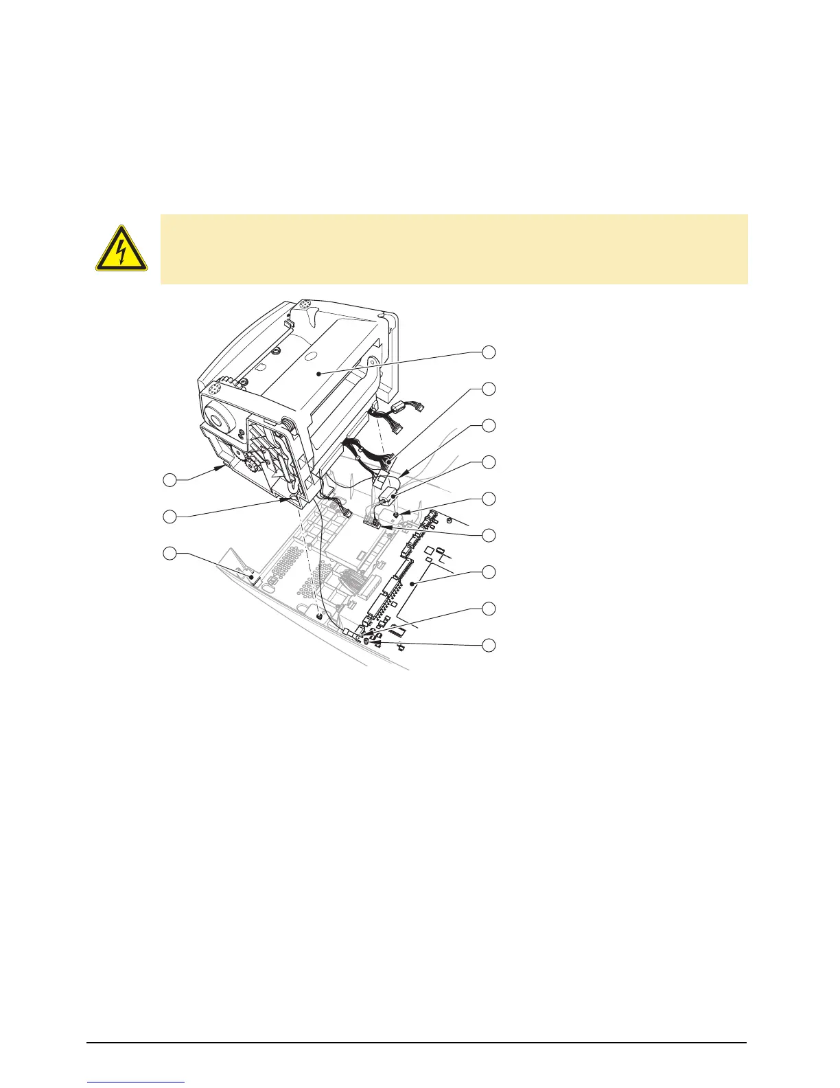
Fig. 5: Replacing the print mechanism
1. Remove the outer casing together with the cover (see section 2.5, items 1 to 4).
2. Disconnect the print mechanism cable (5) from the CPU PCB (7).
3. Loosen the screw (12) and take off the grounding cable (11).
4. Loosen the two screws (8). Slide the print mechanism (4) back a little until the elongated holes (2)
can be lifted off the two screws (8). Pull the lower lugs (1) out of the bottom guides (3) and place the
print mechanism beside the printer.
5. Open the ferrite (7) and pull out the cable (6) from the BDC PCB (9).
6. Push the cable (6) of the new print mechanism (4) into the BDC PCB (9) and re-attach the ferrite (7).
7. Slide the lower lugs (1) of the new print mechanism (4) into the bottom guides (3), press down, and
slide forward until it slots into the projections alongside the screws. Tighten both screws (8).
8. Attach the lug of the grounding cable (11) and tighten the screw (12).
9. Connect the cable (5) to the CPU PCB (10).
10. Remount the outer casing together with the cover.
DANGER!
Danger to life and limb from electric shock!
⇒ Disconnect the device from the mains supply before opening the outer casing.
8
7
6
5
9
10
11
4
12
1
2
3
1 Lug
2 Elongated hole
3 Bottom guide
4 Print mechanism
5 Cable
6 Cable
7 Ferrite
8 Two screws
9 BDC PCB
10 CPU PCB
11 Grounding cable
12 Screw