16 Service Manual Edition 12/07
Replacing assembly units
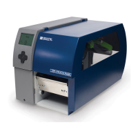
Brady IP Series Printer
2.10 Replacing the drive of the cutting unit
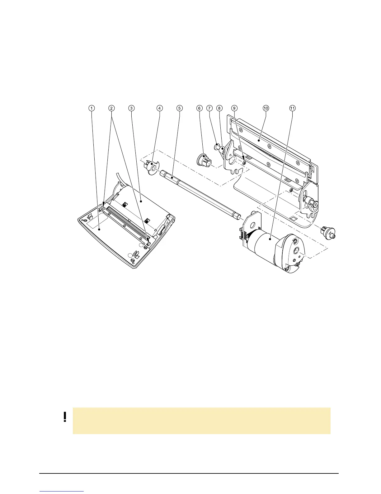
Fig. 9: Replacing the drive of the cutting unit
1. Turn the control panel (1) down, unlock the cutting unit (3) at the both plastic latches (2) and lift it.
2. Loosen the nuts (9).
3. Loosen (but not remove) the two screws (7) carefully so that the connectors (8) can be moved from
the pivots of the eccentrics (6).
4. Unlock the two eccentrics (6) and pull they off from the shaft (5).
5. Unlock the clock wheel (4), pull out the shaft (5) from the drive (11) and the base plate (10).
6. Remove the drive (11) and insert the new drive into the form hole of the base plate (10).
7. Assembly in reverse order.
1
Control panel
2 Two plastic latches
3 Cutting unit
4 Clock wheel
5 Shaft
6 Two eccentrics
7 Two screws
8 Two connectors
9 Base plate
10 Drive
NOTE!
Ensure that the latches of the two eccentrics (6) and of the clock wheel (4) are positioned as shown
in the figure.