Brady IP Series Printer
Replacing assembly units
Edition 12/07 Service Manual 19
2.13 Replacing the BDC PCB
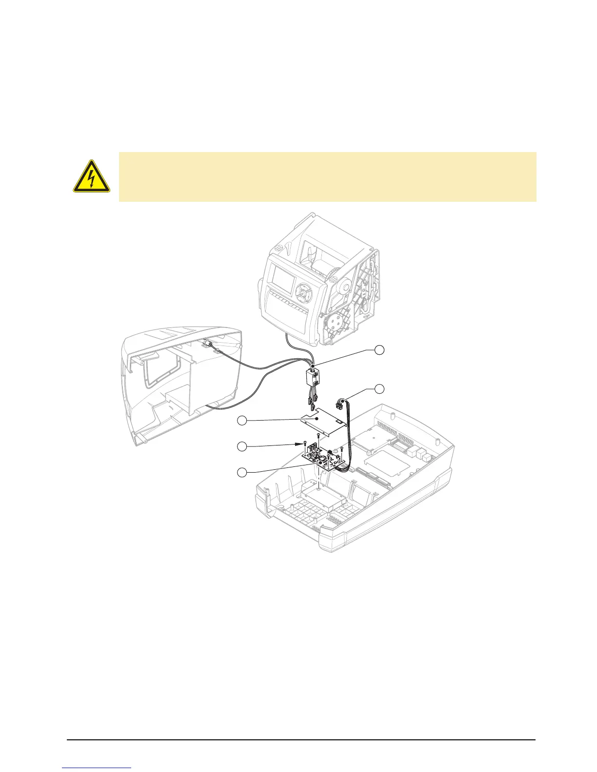
Fig. 12: Replacing the BDC PCB
1. Remove the outer casing (see section 2.5, items 1 to 4).
2. Remount the print mechanism (see section 2.6, item 4) and hing it up.
3. Pull out the three cables (1) and the cable (2) from the BDC PCB.
4. Remove the cover (3).
5. Remove the 4 screws (4).
6. Remove the BDC PCB (5).
7. Mount in reverse order.
DANGER!
Danger to life and limb from electric shock!
⇒ Disconnect the device from the mains supply before opening the outer casing.
1
Three cables
2 BDC main cable
3 Cover
4 4 screws
5 BDC PCB
cancel
pause
menu
feed
5
4
3
2
41