4-14 100-214-239 Rev. A
Installation and Setup
4.6.2 Remote Terminal Connection
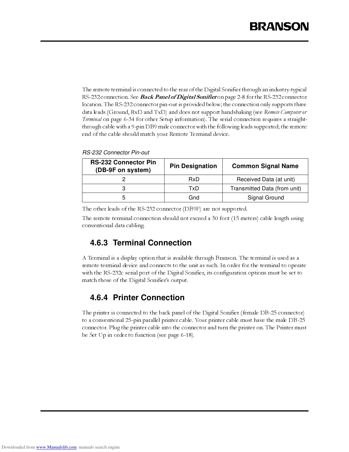
The remote terminal is connected to the rear of the Digital Sonifier through an industry-typical
RS-23 2 co nnect io n. See
Back Panel of Digital Sonifier
on page 2-8 for the RS-232 connector
location. The RS-232 connector pin-out is provided below; the connection only supports three
data leads (Ground, RxD and TxD) and does not support handshaking (see
Remote Computer or
Terminal
on page 6-34 for other Setup information). The serial connection requires a straight-
through cable with a 9-pin DB9 male connector with the following leads supported; the remote
end of the cable should match your Remote Terminal device.
The other leads of the RS-232 connector (DB9F) are not supported.
The remote terminal connection should not exceed a 50 foot (15 meters) cable length using
conventional data cabling.
4.6.3 Terminal Connection
A Terminal is a display option that is a vailable through Branson. The terminal is used as a
remote terminal device and connects to the unit as such. In order for the terminal to operate
with the RS-232c serial port of the Digital Sonifier, its configuration options must be set to
match those of the Digital Sonifier’s output.
4.6.4 Printer Connection
The printer is connected to the back panel of the Digital Sonifier (female DB-25 connector)
to a convention al 25-pin parallel pri nt er cabl e. Your print er cab le must have the male DB- 25
connector. Plug the printer cable into the connector and turn the printer on. The Printer must
be Set Up in order to function (see page 6-18).
RS-232 Connector Pin-out
RS-232 Connector Pin
(DB-9F on system)
Pin Designation Common Signal Name
2 RxD Received Data (at unit)
3 TxD Transmitted Data (from unit)
5 Gnd Signal Ground