100-214-239 Rev. A 4-15
Electrical Connections to Equipment
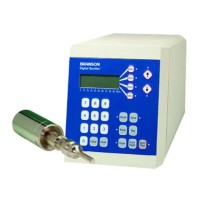
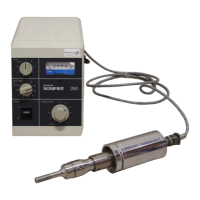
Digital Sonifier
4.6.5 Temperature Probe Connection
The tempera tur e probe is connected to the Digi ta l Sonifier us i ng a 1/4 i nch RCA - type phone
jack connector. The Omega Temperature Probe that is specified matches properly, and is the
only temperature device for use with the Digital Sonifier. The Probe temperature is displayed
(example on page 6-32), or the display will shown TEMP OFF if no probe is connected.
4.6.6 User I/O Connection
The Digital Sonifier is equipped with a standard external connection to allow you to design and
connect your own custom interface for controlling the unit. The User I/O interface can be use-
ful when you need to activate the Sonifier remotely, for example, when the operator must start
and stop the unit from another room for safety reasons.
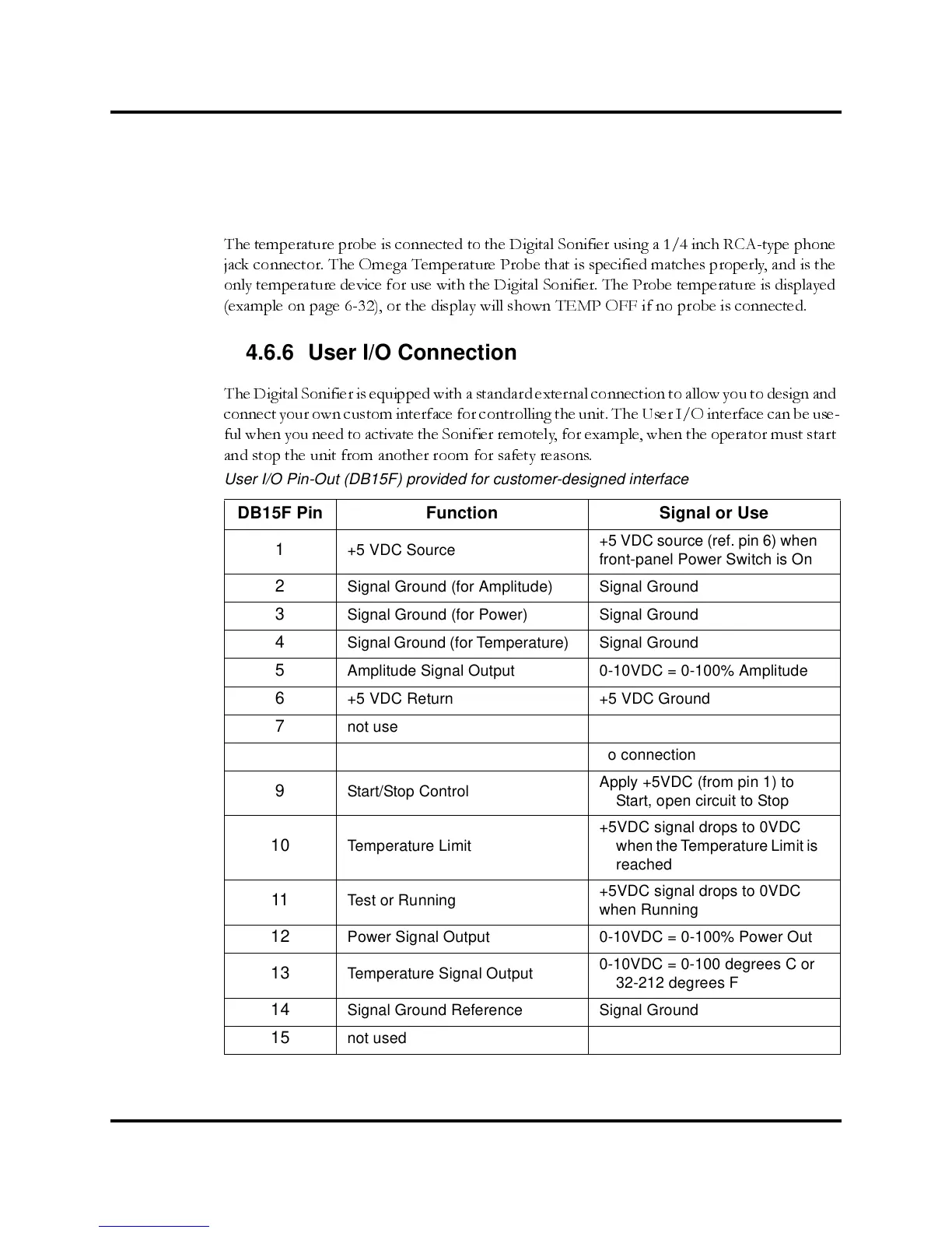
User I/O Pin-Out (DB15F) provided for customer-designed interface
DB15F Pin Function Signal or Use
1
+5 VDC Source
+5 VDC source (ref. pin 6) when
front-panel Power Switch is On
2
Signal Ground (for Amplitude) Signal Ground
3
Signal Ground (for Power) Signal Ground
4
Signal Ground (for Temperature) Signal Ground
5
Amplitude Signal Output 0-10VDC = 0-100% Amplitude
6
+5 VDC Return +5 VDC Ground
7
not used no connection
8
not used no connection
9
Start/Stop Control
Apply +5VDC (from pin 1) to
Start, open circuit to Stop
10 Temperature Limit
+5VDC signal drops to 0VDC
when the Temperature Limit is
reached
11 Test or Running
+5VDC signal drops to 0VDC
when Running
12 Power Signal Output 0-10VDC = 0-100% Power Out
13
Temperature Signal Output
0-10VDC = 0-100 degrees C or
32-212 degrees F
14
Signal Ground Reference Signal Ground
15
not used no connection