SERIES 70 ELECTRIC ACTUATOR
Installation, Operation, and Maintenance Manual
37 of 48
© 2022 BRAY INTERNATIONAL, INC. ALL RIGHTS RESERVED. BRAY.COM
The Information contained herein shall not be copied, transferred, conveyed, or displayed in any manner
that would violate its proprietary nature without the express written permission of Bray International, Inc.
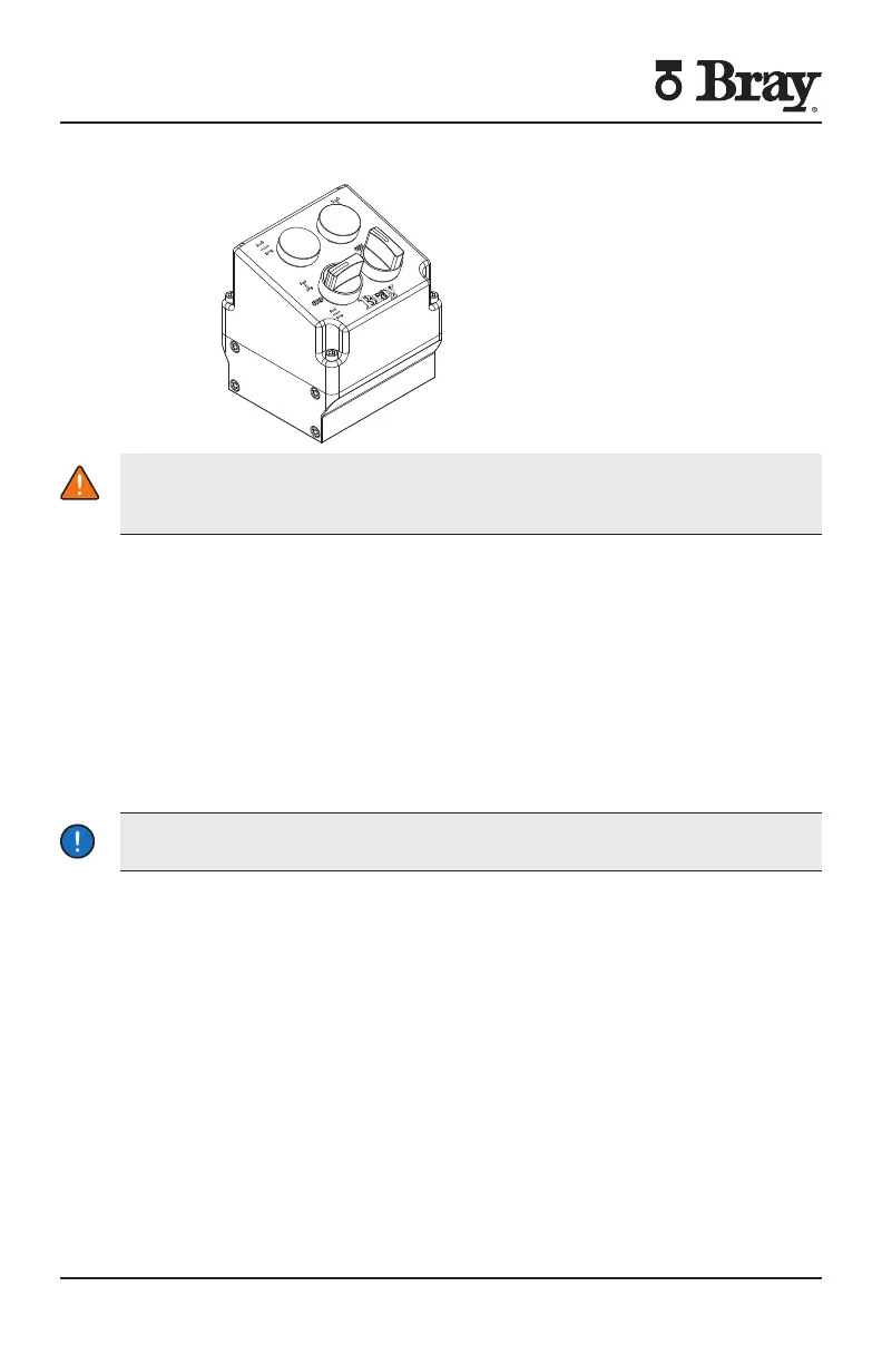
Local Control Station Installation Procedure
WARNING
Turn o all power and lockouttag out service panel before installing or modifying
any electrical wiring
The local control station is mounted to the S against the conduit openings using
pre-drilled and tapped mounting holes
1. Remove the S70 actuator cover and set aside in a safe location.
2. Remove all conduit plugs and external connections on the S70 that may already
be in place.
3. Remove 4 short bolts and washers that were pre-installed on the exterior of the
S70 base, surrounding the conduit entries.
4. Adhere the gasket to the control station base.
5. Slide o-rings onto the long mounting bolts until flush with bottom of bolt head.
6. Mount the control station to the actuator using the 4 mounting bolts.
7. Wire the control station to the actuator in accordance to the wiring diagram
provided.
NOTICE
Power and control wiring should use separate conduit entries
NOTES
The local control station contains no terminal strips and all wiring is direct to the
switches and lights via x ¾” NPT or holes in bottom of housing
Ordering the control station with optional pin connector receptacles will
eliminate the necessity of field wiring Not all possible options are available with
receptacles Consult factory
Control station will be completely factory wired and tested
Factory will need wiring diagram drawing number of the existing unit if it is to be
retrofit with a local control station New wiring diagram will be provided based
upon this information
Local control station can be ordered with key lockable switches
Local control station requires a dedicated set of auxiliary switches These
switches are required for turning on or o the lights on the control station to
locally indicate actuator position
Alternative mounting kit can be ordered in case it is preferred to mount the
control station nearby but not on the S actuator

 Loading...


