18 67XXU USB/Serial Scale Service Manual
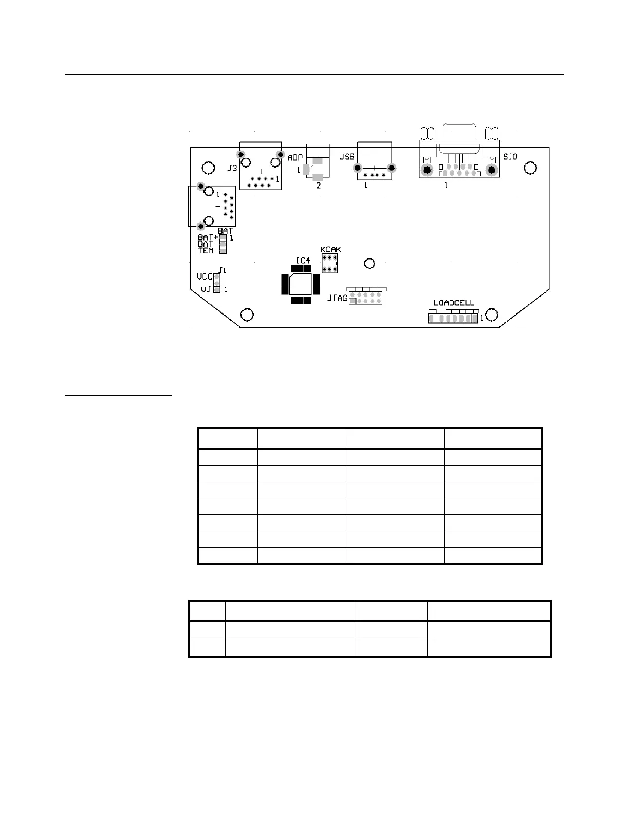
2.5 Mainboard
Figure 2.23 shows the main board connectors for the loadcell, RS-232 port, USB port,
power supply and battery.
Figure 2.23 67XXU Main Circuit Board
2.5.1 Definition of Connectors and Jumpers
Table 2.1 Loadcell Connector
Table 2.2 Adapter Power Input Connector (ADP)
Pin Description In/Out/Power Electrical Level
1 + excitation power output 5±0.3 VDC (≤0.12A)
2 + sense power input 5±0.3 VDC
3 - excitation power ground 0 VDC
4 - sense power input ≤0.5 VDC
5 + signal signal input 2.5±0.3 VDC
6 - signal signal input 2.5±0.3 VDC
7shield - -
Pin # Definition In/Out/Power Electrical Level
1 Adapter input voltage - (GND) Power ground 0VDC
2 Adapter input voltage + Power input
6.5 VDC (6-9VDC,
≥0.5A)