© 2022 Brivo Systems LLC. All rights reserved. PUB-Brivo ACS6100 Installation Manual
30
Brivo ACS6100 Installation Manual
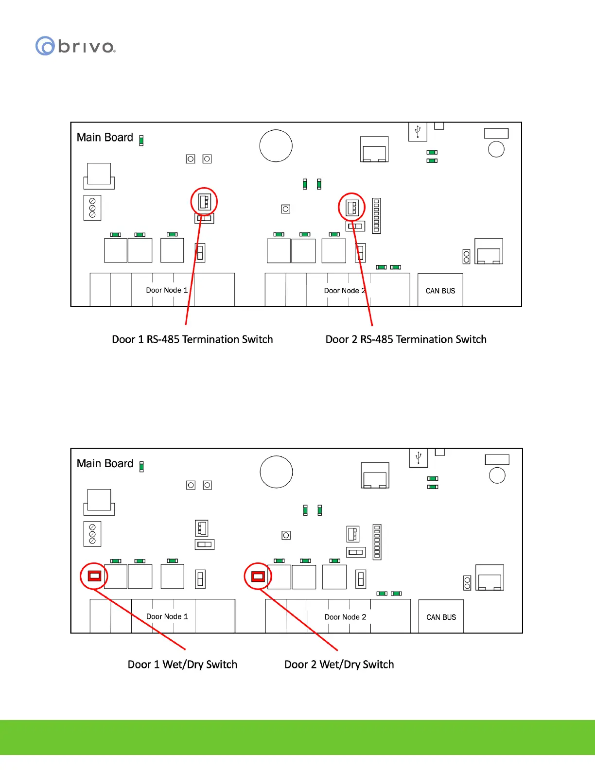
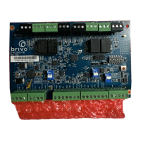
NOTE: RS-485 bus requires termination. Door 1 RS-485 Term is the RS-485 Door 1 bus termination switch and
Door 2 RS-485 Term is the RS-485 Door 2 bus termination switch. To enable RS-485 bus termination for Door 1, put
the RS-485 termination switch in the Enabled position. To enable RS-485 termination for Door 2, put the RS-485
termination switch in the Enabled position.
Figure 23 - RS-485 Termination Switch Locations for Doors 1 and 2
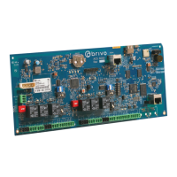
NOTE: Door lock relays can be provided with power by using Door 1 Wet/Dry Switch above Door Node 1 and Door
2 Wet/Dry Switch above Door Node 2. To enable wet mode for Door 1, put the Door 1 Wet/Dry Select Switch in the
Wet position. To enable wet mode for Door 2, put the Door 2 Wet/Dry Select Switch in the Wet position. To enable
dry mode for Door 1, put the Door 1 Wet/Dry Select Switch in the Dry position. To enable dry mode for Door 2, put
the Door 2 Wet/Dry Select Switch in the Dry position.
Figure 24 - ACS6000 Wet/Dry Door Contact Switches for Doors 1 and 2