Brocade FastIron X Series Chassis Hardware Installation Guide 5
53-1001723-02
Hardware features
1
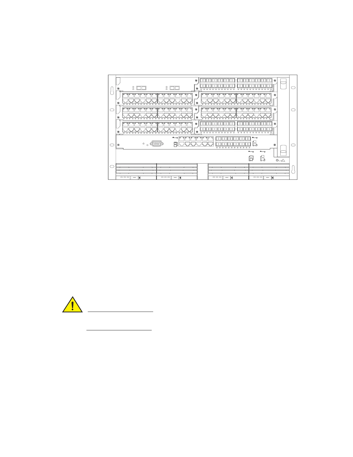
Figure 1 shows the FSX chassis.
FIGURE 1 FSX chassis
Upon shipment from the factory, the following components are installed in the FSX chassis:
• A slot panel in each interface module slot and power supply slot that does not currently have a
module or power supply installed in it. The slot panel ensures proper airflow within the chassis.
• One or two AC or DC power supplies
• A fan tray assembly which contains the cooling system for the chassis
In the FSX slots, you can install the following:
• One management module
• Up to eight interface modules
• Up to four AC and DC power supplies: two system (12-volt) power supplies and two POE (48- or
220-volt) power supplies
Before installing any modules or power supplies, you must remove the slot panel.
If you do not install a module in a slot, you must keep the slot panel in place. If you run the
chassis with an uncovered slot, the system will overheat.
DC OK ALMAC OK DC OK ALMAC OK DC OK ALMAC OK DC OK ALMAC OK
8X-12GM-4
Console
Pwr
Lnk
Odd
Even
Odd
Even
Lnk
424F
424C
42XG
424C
424C424C
424F
424C
Odd
Even
Lnk
Lnk
Odd
Even
POE
424C
424F
SYSEJECTSYSEJECTSYSEJECTSYSEJECT
Lnk
Act
Lnk
Act
12
FastIron SuperX

 Loading...