Brocade FastIron X Series Chassis Hardware Installation Guide 17
53-1001723-02
Hardware features
1
If you attach both the copper and fiber connectors for a port to the network, the fiber connector
takes precedence over the copper connector. These ports support true media automatic detection,
meaning the device selects the fiber or copper connector based on link availability. If a fiber link
cannot be established, the device selects the copper media.
Typical uses of these ports include but are not limited to the following:
• Connecting a PC through which you can access the system directly or through a Telnet
connection and configure, monitor, and manage the FSX system.
• Connecting a Gigabit Ethernet switch, which will provide connectivity to your existing
management network. You can then access the FSX system and configure, monitor, and
manage the system from a management station.
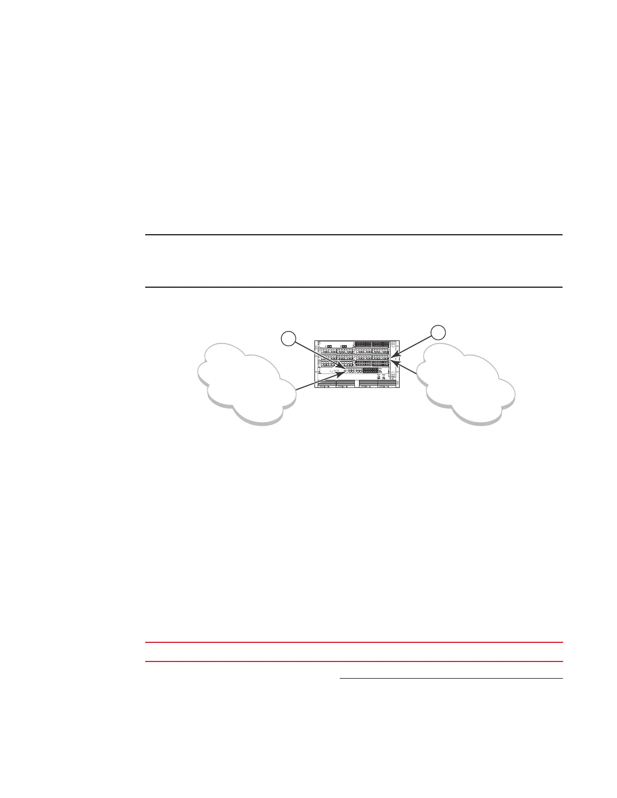
The existing management networks into which you can connect the Gigabit Ethernet ports must be
separate and isolated from the network over which user packets are switched and routed as shown
in Figure 10.
FIGURE 10 Separate management and switching or routing networks
LEDs on the FSX management module
The FSX management module provides status information using the LEDs listed in Table 5. The
location of the LEDs is as follows:
• The fiber connectors use the LEDs located beneath the mini-GBIC slots.
• The copper connectors use square LEDs located in the upper right and left corners of the
upper Gigabit copper connectors. The LED on the left side is for the upper copper connector.
The LED on the right side is for the lower copper connector.
Table 5 describes the LEDs on the FSX management module.
1 Management port
2Interface port
TABLE 5 FSX management module LEDs
LED Description and Position State Meaning
Pwr Round LED located to the left
of the console port
On (Green) The module is receiving power.
Off The module is not receiving power.
t
FastIron Super X
d
SYSEJECTSYSEJECTSYSEJECTSYSEJECT
2
1
FastIron SuperX
Management
Network
Switching and
Routing Network

 Loading...