System status LEDs (Continued)TABLE 9
LED Condition Status
Diag
(Diagnostic)
Flashing Green System self-diagnostic test in progress.
Green System self-diagnostic test successfully completed.
Amber System self-diagnostic test has detected a fault.
(Blower, thermal or any interface fault.)
A or S
(Active or Standby)
Green The device is the Active controller. If this LED is
flashing green, the system is initializing.
Amber Indicates the device is the Standby controller.
Off Device is operating as a stack member, or is in
standalone mode.
Up Link or Down Link (Stacking uplink or
downlink port status)
Green Uplink is operating normally.
Off Uplink has failed or there is no link.
Stack ID (1-8) Green Indicates the device stack ID.
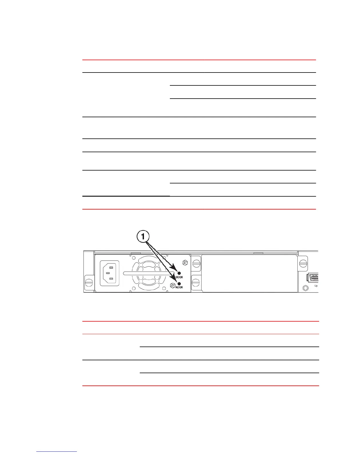
FIGURE 20 Power status LEDs
1. Power status LEDs
Power status LEDs TABLE 10
LED Condition Status
DC OK Green DC output ok
Red DC output fail
AC OK Green AC input ok
Off AC input fail
Product Overview
Brocade FCX Series Hardware Installation Guide 27
53-1002977-01

 Loading...


