NOTE
Both "AC OK" and "DC OK" LEDs must be green for the device to function normally.
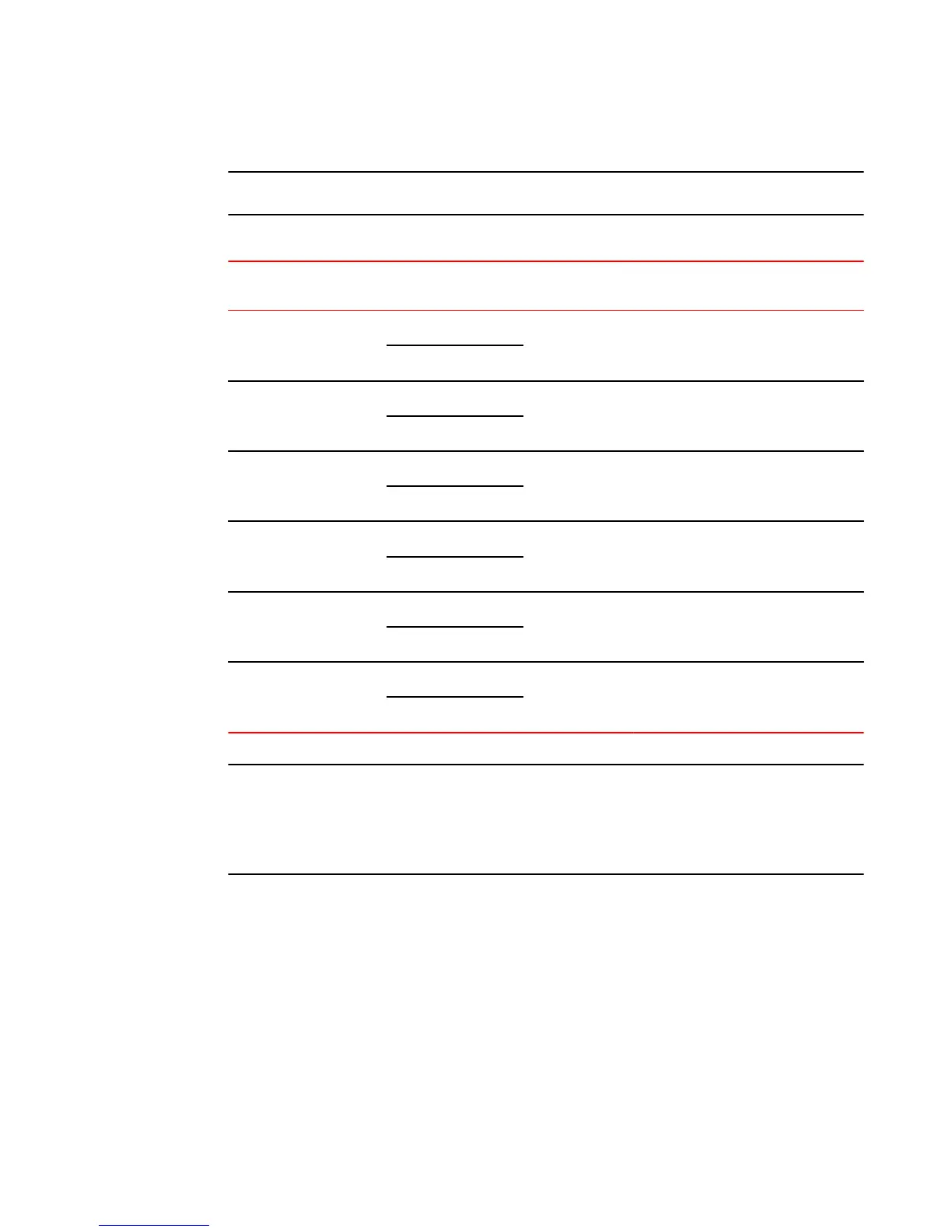
Switch status for two installed power supply units TABLE 11
State LED PSU1 PSU2 Switch Status Load Sharing HPOE Budget(HPOE
models only)
Four Green PSU LEDs AC OK Green Green Running Yes 820W
DC OK Green Green
Single Red ‘DC OK’ LED AC OK Green Green Running No 410W
DC OK Green Red
Both ‘DC OK’ LEDs Red AC OK Green Green Failure No None
DC OK Red Red
One PSU with both ‘AC
OK’ ‘DC OK’ LEDs Off
AC OK Green Off Running No 410W
DC OK Green Off
‘DC OK’ LEDs Red and
Off
AC OK Green Off Failure No None
DC OK Red Off
All ‘AC OK’ LEDs Off AC OK Off Off Power Off or
Failure
No None
DC OK Off Off
NOTE
When two 620W power supplies are installed in an HPOE system that has no load or light load on the
POE function, one of two power supplies may have its "DC OK" LED light red. There is no fault in the
power supply or the system and the switch is functioning normally. The LED will turn to green
automatically once the load is increased over the minimum load requirement. In configurations with a
single power supply installed the "DC OK" LED will light green in a no-load or light-load condition.
Product Overview
28 Brocade FCX Series Hardware Installation Guide
53-1002977-01

 Loading...


