Port, system, and power status LEDs for Brocade FCX 624-E, FCX 624-I, FCX 648-E, and FCX
648-I
FCX switches include a display panel for key system and port indicators that simplifies installation and
network troubleshooting. The LEDs are located on the front panel for easy viewing.
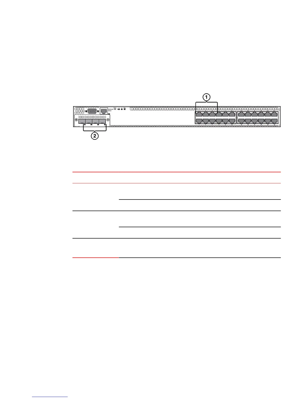
FIGURE 21 Port status LEDs
1. Port status LEDs
2. SFP or SFP+ port status LEDs
Port status LEDs TABLE 12
LED Condition Status
Ethernet(1~24/48)
Link or Activity or Speed
On/Flashing Green The port has established a valid link at 10/100/1000 Mbps. Flashing
indicates the port is transmitting and receiving user packets.
Off A link is not established with a remote port.
SFP(1F~4F)
Link or Activity
On/Flashing Green The SFP port has established a valid 100/1000 Mbps link. Flashing
indicates the port is transmitting and receiving user packets.
Off A link is not established with a remote port.
SFP+(1F~4F)
Link or Activity
On/Flashing Green The SFP+ port has established a valid 10 Gbps link. Flashing
indicates the port is transmitting and receiving user packets.
Port, system, and power status LEDs for Brocade FCX 624-E, FCX 624-I, FCX 648-E, and FCX 648-I
Brocade FCX Series Hardware Installation Guide 29
53-1002977-01

 Loading...


