49
Outboard Installation
Transom Measuring and Drilling
3
Transom Height
Make sure the transom height matches the length
of the outboard to be installed.
• A 19 to 21 in. (48.3 to 53.3 mm) transom height
uses a 20 in. (50.8 mm) shaft outboard.
• The shaft length of the outboard being installed
should come close to matching the transom
height of the boat.
• Refer to SPECIFICATIONS in outboard Opera-
tor’s Guide for transom height.
Determine transom height by measuring from the
top edge of the transom, along the centerline.
For dual-outboard installations, transom height
should be measured at the outboard centerlines.
Use a straightedge as a reference to extend the
bottom of the boat.
Position the straightedge along centerline. The
distance from the top edge of the straightedge to
the top edge of the transom is the actual transom
height.
Transom Drilling Locations
All models use the standard ABYC 4-Bolt mount-
ing pattern.
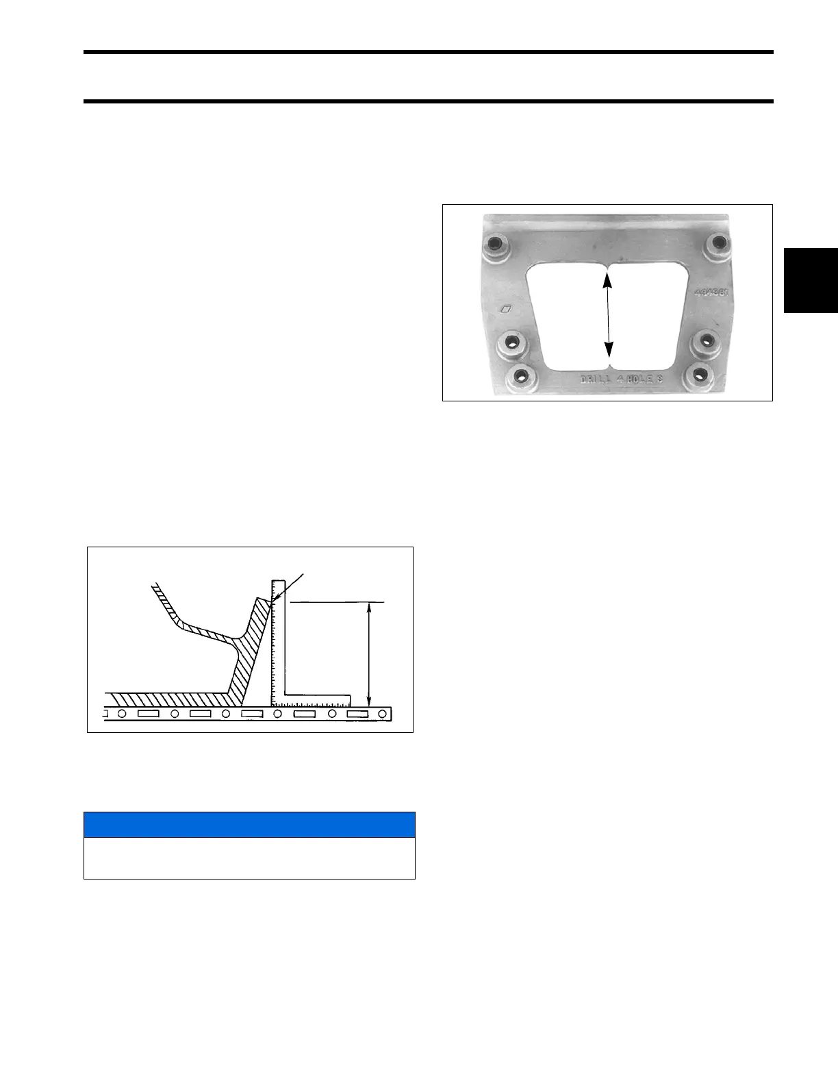
Use Transom drill fixture, P/N 434367 or
P/N 385368, as a guide for correct hole place-
ment. If drill fixture is unavailable, refer to Drilling
and Hardware Diagrams on p. 50 for measure-
ments.
Position drill fixture on top of transom or bracket
and align indicator points with centerline.
The indicators are affected by the squareness of
the top edge of the transom. If either side of the
fixture must be raised more than ¼ in. (6 mm)
above the transom's top surface to make both
indicators align, the transom must be modified.
IMPORTANT: DO NOT assume that the top
edge of the transom is straight. Position the drill fix-
ture based on measurements aligning it to the bot-
tom of the hull.
Before drilling any mounting holes:
• Make sure the hole locations provide enough
clearance for mounting bolts and washers.
• Check the inside area of the transom for
obstructions.
• Check transom height(s) at centerlines.
Drill four ½ in. (13 mm) mounting holes in the
appropriate locations.
IMPORTANT: Be sure to drill the required holes
perpendicular to transom surface.
Mount the centerline of the outboards at least 28
in. (711.0 mm) apart to eliminate interference at all
tilt and steering angles.
1. Top edge of transom
2. Actual transom height
DR5541
NOTICE
Maintain at least 1.75 in. (45 mm) of transom
surface above the top mounting bolts.
Transom drill fixture P/N 434367 (heavy duty)
24496