50
Outboard Installation
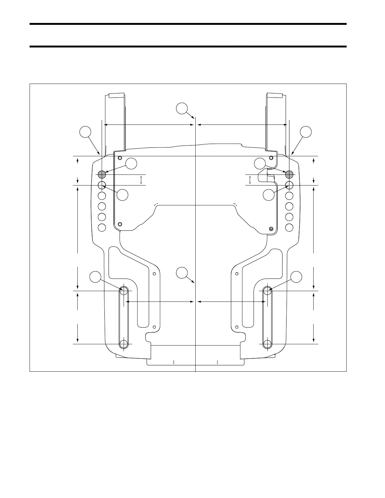
Transom Measuring and Drilling
Drilling and Hardware Diagrams
IMPORTANT: This is not a template.
Quantity
1. Center of Transom 5. Bolt * 4 * Choose from the following bolt sizes:
2. Top of Transom 6. 318272 Plate 2 318573 3 1/2 in. (89 mm)
3. 1/2” Bolt Hole Locations 7. 318273 Retainer 4 336676 4 1/2 in. (114 mm)
4. Optional Mounting Location 8. 319886 Screw 2 331578 5 in. (127 mm)
9. 307238 Washer 4 354101 6 in. (152 mm)
10. 320248 Washer 4 354102 7 in. (178 mm)
11. 313623 Nut 4 354103 8 in. (203 mm)
12. 318572 Cap 354104 9 in. (229 mm)
7-1/4 in.
(184.7mm)
7-1/4 in.
(184.7mm)
2 in.
(50.8mm)
2 in.
(50.8mm)
4-15/16 in.
(125.4mm)
4-15/16 in.
(125.4mm)
6-7/16 in.
(163.5mm)
6-7/16 in.
(163.5mm)
3-5/8 in.
(92.6mm)
3-5/8 in.
(92.6mm)
3/4 in. (18.5mm) 3/4 in. (18.5mm)
2
3
4
2
3
4
33
1
1
009097