29
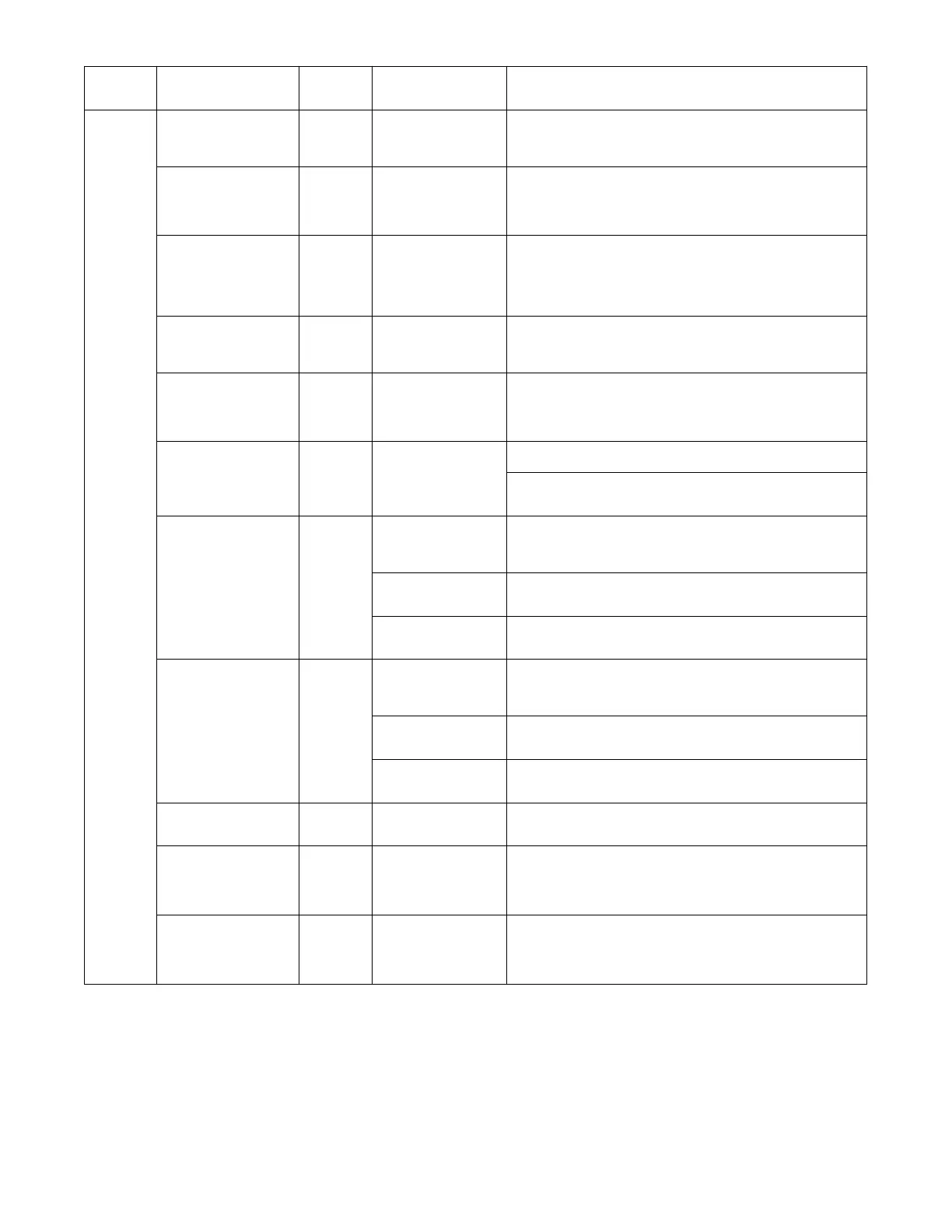
Table 12 -- Menu Structure* (cont)
Menu Parameter
Parameter
Default
Value
Parameter
Range and Increment
[
EXPANDED P ARAMETER NAME
Notes
SETPOINTS
MAT SET 53_F
(12_C)
38 to 70_F;
(3 to 21_C)
increment by 1
SUPPLY AI R SETP OINT
Setpoi nt determines where the economizer will modulate the OA damper to
maintain the mixed air temperature.
SeeMenuNote2.
LOW T LOCK 32_F
(0_C)
---45 to 80_F;
(---43 to 27_C)
increment by 1
COMPRESSOR LOW TEMPERATURE LOCKOUT
Setpoi nt determines outdoor temperature when the mechanical cooling
canno t be turned on. Commonly referred to as the Comp ressor lock out. At
or below the set p o int the Y1---O and Y2---O will not be energ ized on the
cont ro lle r.
DRYBLB SET 63_F
(17_C)
48 to 80_F
(9 to 27_C)
increment by 1
OA DRY BULB TEMPERATURE CHANGEOVER SETPOINT
Setpoi nt determines where the economizer will assume outdoor air
temperature is good for free cooling; e.g.: at 63_F(17_C), unit will
economize at 62_F (16.7_C) and below and not economize at 64_F
(17.8_C) and above. There is a 2_F(1.1_C) deadband.
SeeMenuNote3
ENTH CURVE ES3 ES1, ES2, ES3, ES4, or
ES5
ENTHALPY CHANGEOVER CURVE
(Re q uires enthalpy sens o r opt ion)
Enthalp y bounda ry “curv e s” for econom izing using si ngle enthalp y.
See pag e 36 for des c ription of entha lp y curve s.
DCV SET 1100ppm 500 to 2000 ppm;
increment by 100
DEMA N D CONTROLLED VENTILATION SETPO INT
Displays only if CO
2
se nsor is connec ted. Setp o int for Demand Controlled
Ventilation of space. Above the setpoint, the OA dampers will modulate
open to bring in additi onal OA to maintain a space ppm level below the
setpoint.
MIN POS 2.8 V 2to10Vdc
VENTILATION MINIMUM POSITION
Displays ONLY if a CO
2
se nsor is NOT co nnected .
Wit h 2 ---sp eed fan uni ts MIN POS L (low speed fan) and MIN POS H (hi gh
speed fan) setti ngs are required. Default for MIN POS L is 3.2V and MIN
POS H is 2.8V.
VENTMAX 2.8 V
2to10Vdc DCV MAXIMUM DAMPER POSITI ON
Displays only if a CO
2
se nsor is conne c ted. Used for Vbz (vent ilati o n max
cfm) setpoint. VENTMAX is the same setting as MIN POS would be if you
did not have the CO
2
sensor .
100 to 9990 cfm
increment by 10
IfOA,MARAandCO
2
se ns o rs are connec t e d and DCV CAL ENABLE is
set to A UTO mode, the OA dampers are controlled by CFM and di sp lays
from 100 to 9990 cfm.
2to10Vdc Wit h 2 ---speed fan units VENTMAX L (low speed fan) and VENTMAX H
(high speed fan) settings are required. Default for VENTMA X L is 3.2V and
VENTMAX H is 2.8V.
VENTMIN 2.25 V
2to10Vdc DCV MINIMUM DAMPER POSITION
Displays only if CO
2
sensor is connected. Used for Va (ventilation min cfm)
se t point . This is the ventilati o n requirement for less than maximum
oc c upancy of the space.
100 to 9990 cfm
increment by 10
IfOA,MARAandCO
2
se ns o rs are connec t e d and DCV CAL ENABLE is
set to A UTO mode, the OA dampers are controlled by CFM and di sp lays
from 100 to 9990 cfm.
2to10Vdc With 2--- speed fan units VENTMIN L (low speed fan) and VENTMIN H
(high speed fan) settings are required. Default for VENTMIN L is 2.5V
and VENTMIN H is 2.25V.
ERV OAT SP
[[
32_F
(0_C)
0to50_F;
(---18 to 10_C)
increment by 1
ENERGY RECOVERY VENTILATION UNIT OUTDOO R AIR TEMPERATURE
SETPOI NT
Only when AUX1 O = ERV
EXH1 SET 50% 0 to 100%;
Increment by 1
EXHAUST FAN STAGE 1 SETPOINT
SetpointforOAdamperpositionwhenexhaustfan1ispoweredbythe
economizer.
Wit h 2 ---speed fan uni ts Exh1 L (low speed fan) and Exh1 H (high speed
fan) settings are required. Default for Exh1 L is 65% and Exh1 H is 50%
EXH2 SET 75% 0 to 100%;
Increment by 1
EXHAUST FAN STAGE 2 SETPOINT
SetpointforOAdamperpositionwhenexhaustfan2ispoweredbythe
economizer. Only used when AUX1 O is set to EHX2.
Wit h 2 ---speed fan uni ts Exh2 L (low speed fan) and Exh2 H (high speed
fan) settings are required. Default for Exh2 L is 80% and Exh2 H is 75%
 Loading...