30
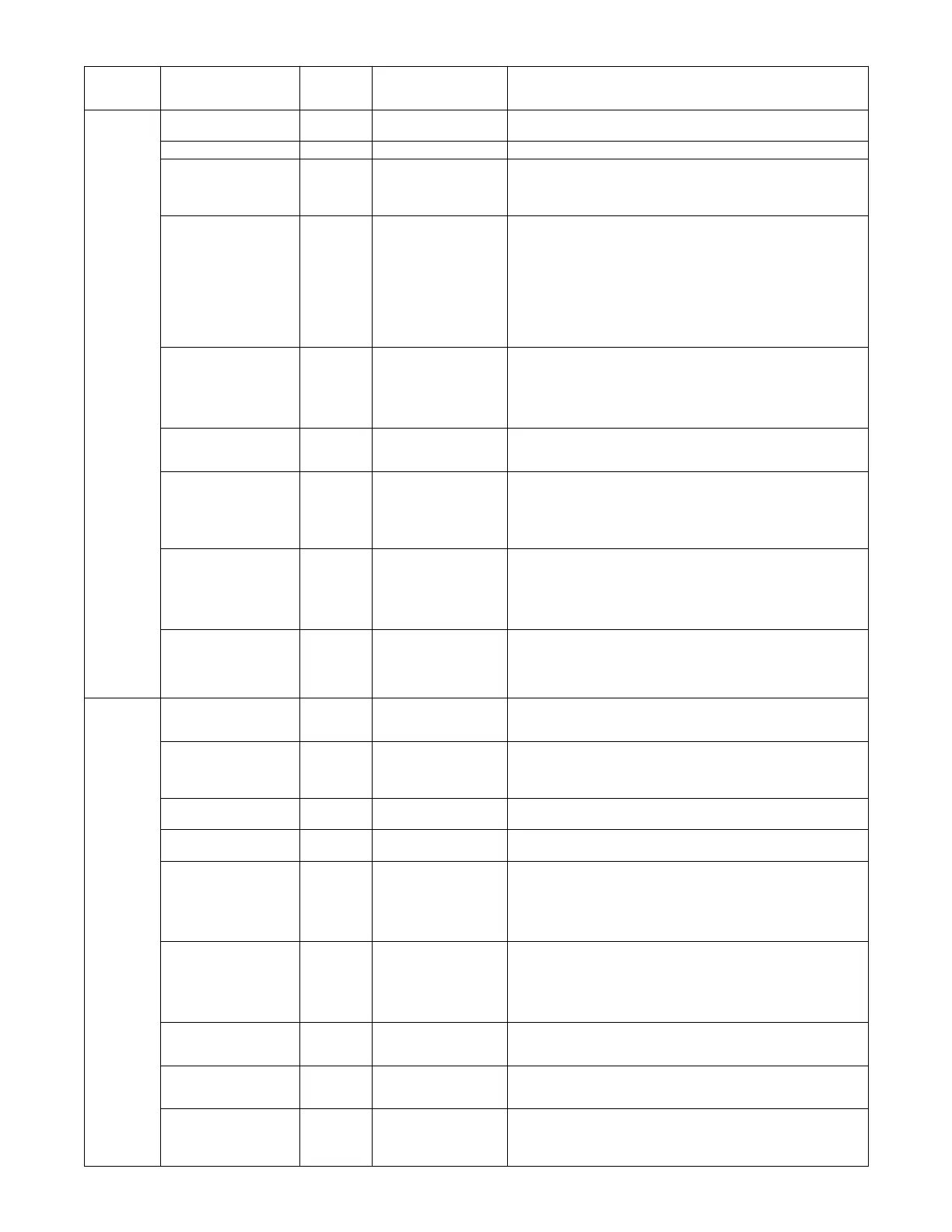
Table 12 -- Menu Structure* (cont)
Menu Parameter
Parameter
Default
Value
Parameter
Range and Increment
[
EXPANDED P ARAMETER NAME
Notes
SYSTEM
SETUP
INSTALL 01/01/10 Display order = MM/DD/YY
Setting order = DD, MM, then YY.
UNITS DEG _F _For_C Sets economizer controller in degrees Fahrenheit or Celsius.
EQUIPMENT CONV Conventional or HP CO N V = conve nt ional;
HP O/B = Enable Heat Pump mode. Us e AUX2 I for Heat Pump input from
therm ostat or controlle r.
SeeMenuNote4
AUX2 IN n/a Shutdown (SD)
Heat (W1)
HP (O)
HP (B)
In CONV mode:
SD = Enable s configuration of shutd o w n (de fa ult );
W = Informs controller that system is in heating mode.
NO T E : If usi n g 2--- speed fan mode, you must progr a m CONV mode
forW.Shutdownisnotavailablein2---speedfanmode.
SeeMenuNote4.
In HP O/B mode:
HP(O) = energi ze heat pump on Cool (default);
HP(B) = energize heat pump on Heat.
FAN SPEED 1speed 1 speed/
2 speed
Sets economizer controller for operation of 1 speed or 2 speed supply fan.
The controller does not control the fan but posi t ions the OA and RA
dampers to the heating or cooling mode. See page 31 for modes and
position.
NO TE: 2---speed fan optio n also need s Heat (W1) programmed in
AUX 2 In. See Menu Note 4.
FAN CFM 5000cfm 100 to 15000 cfm;
increment by 100
UNI T DESIG N AIRFL O W (CFM)
Enter ON LY if using DCVCA L ENA = A UTO
The value is found the nameplate label for the specific RTU.
AUX1 OUT NONE NONE
ERV
EXH2
SYS
Select OUTPUT for AUX1 O relay
NONE = not configured (output is not used)
ERV = Energy Recovery Ventilator
[[
EXH2 = second damper position 24 Vac ou t for second exhaust fan
SYS = use output as an alarm signal
OCC INPUT INPUT or ALWAYS O CCUPIED MODE B Y EXTERNA L SIG N AL
When using a set b a c k thermostat wi t h occupancy out (24 V ac), the 24 Va c
is input “INPUT” to the OCC terminal. If no occupancy output from the
thermostat then change program to “ALW AYS” OR add a jumper from
termi nal R to OCC terminal.
SeeMenuNote1.
FACTORY DEFAULT NO NO or YES Resets all set points to factory defaults when set to YES. LCD will briefly
flas h YES and change to NO but all para m e t e rs wi ll chang e to the facto ry
de fault values .
NO T E : RECHECK AUX2 IN and FA NTYP E for requ i r ed 2--- speed
values.
ADV AN CED
SETUP
MA LO SET 45_F
(7_C)
35 to 65_F;
(2 to 18_C)
Incremented by 1_
SUPPL Y AIR TEMPERA TURE LOW LIMIT
Temperature to activat e Freeze Protecti on (close damper and alarm if
tem p e rature falls belo w setup value)
FREEZE POS CLO CLO or MIN FREEZE PROTECTION DAMPER POSITION
Damper posi ti on when freeze protecti on is ac ti ve
CLO = closed
MIN = MIN POS or VENTMAX
CO2 ZERO 0ppm 0 to 500 ppm:
Increment by 10
CO
2
ppm level to match CO
2
sensor start level.
CO2 SPAN 2000ppm 1000 to 3000 ppm;
Increment by 50
CO
2
ppm span to match CO
2
sensor. e.g.; 500---1500 sensor output would
be 500 CO
2
zero and 1000 CO
2
span.
STG3 DLY 2.0h 0 min, 5 min, 15 min,
then 15 min intervals.
Up to 4 h or OFF
COOLING STAGE 3 DELA Y
Delay after stage 2 for cool h as been active. Turn s on second stage of
mechanical cooling when economizer is first stage call and mechanical
cooling is second stage call. Allows th r ee stages of cooling, 1
economizer and 2 mechanical.
OFF = no Stage 3 cooling.
SD DMPR POS CLO CLO or OPN Indic a t es shut d o w n si g na l from spa c e thermos t a t or unit ary cont ro lle r.
When controller receives 24 Vac input on the SD terminal in conventional
mode, the OA damper will open if programmed for OPN and OA damper
wil l c l ose if progr a m m e d f o r C LO. Al l oth e r c o n trol s , e . g., Y1 --- O, Y2 --- O,
EXH1,etc.willshutoff.
NOTE: Function NOT AVAILABLE with 2--- speed mode
DA LO ALM 45_F
(7_C)
NONE
35 to 65_F; (2 to 18_C)
Incremented by 5_
UsedforalarmforwhentheDAairtemperatureistoolow.Setlowerrange
of alarm, below this tempe rat ure the alarm will show on the di s p lay.
DA HI ALM 80_F
(27_C)
NONE
70 to 180_F; (21 to 82_C)
Incremented by 5_
UsedforalarmforwhentheDAairtemperatureistoohigh.Sethighrange
of alarm, above this temperature the alarm will show on the dis play
DCVCAL ENA MAN MAN (manual)
AUTO
Turns on the DCV automat ic contro l of the dam p e rs. Resets venti la t ion
based on the RA, OA and MA sens o r cond itio ns. Requires all sensors (RA,
OA, MA and CO
2
).
NOT E: This operation is not operable with a 2---speed fan unit.
 Loading...