2-70 2005 Buell Firebolt: Chassis
HOME
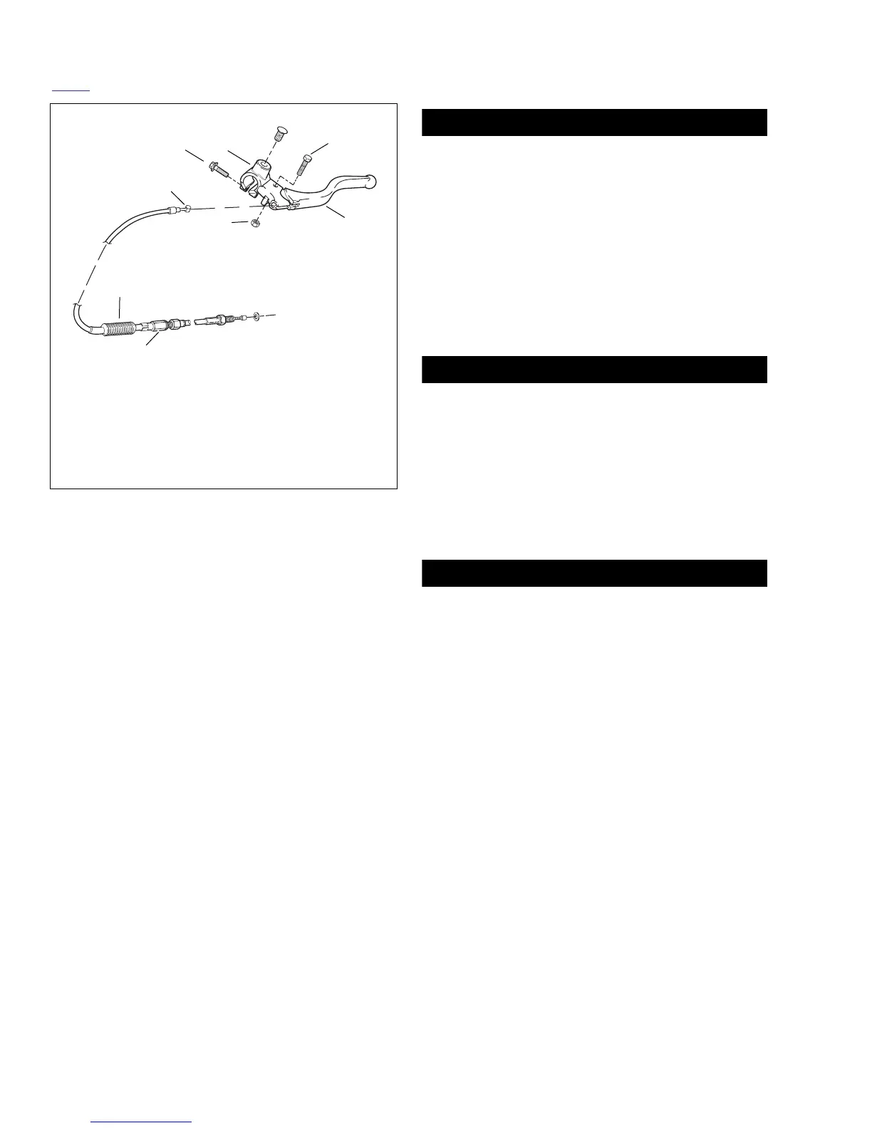
8. See Figure 2-101. Connect clutch cable ferrule (7) to
hand lever (4).
9. Adjust clutch adjusting screw. See 1.9 CLUTCH.
10. Add SPORT-TRANS FLUID (Part No. 99896-88 quart
size; Part No. 99895-88 gallon size) if needed as
required until fluid level is even with bottom of clutch dia-
phragm spring. See TRANSMISSION FLUID under 1.9
CLUTCH.
NOTE
Each time the clutch inspection cover is removed the gasket
must be replaced.
11. Install
new
clutch cover gasket.
12. See Figure 2-97. Install clutch inspection cover (4) with
three TORX screws with washers. Tighten screws in a
crosswise pattern to 84-108
in-lbs
(9.5-12.2 Nm).
CAUTION
Always connect front tie bar to engine mount first.
13. Install front tie bar, P clamp and clutch cable to front
engine mount and tighten fastener to 25-27 ft-lbs (33.9-
36.6 Nm).
14. Connect front tie bar to "V" bracket and tighten fastener
to 25-27 ft-lbs (33.9-36.6 Nm).
15. Adjust clutch cable. See 1.9 CLUTCH.
16. Install wire form and clutch cable to front isolator and
tighten fastener.
17. Install cable strap to voltage regulator wire.
11WARNING1WARNING
Connect positive (+) battery cable first. If positive (+)
cable should contact ground with negative (-) cable con-
nected, the resulting sparks can cause a battery explo-
sion, which could result in death or serious injury.
(00068a)
18. Install chin fairing. See 2.33 CHIN FAIRING.
19. Connect negative battery cable to battery terminal.
Tighten fastener to 72-96
in-lbs
(8-11 Nm).
11WARNING1WARNING
After installing seat, pull upward on front of seat to be
sure it is in locked position. While riding, a loose seat can
shift causing loss of control, which could result in death
or serious injury. (00070a)
20. Install seat. See 2.38 SEAT.
Figure 2-101. Clutch Hand Control Assembly
1. Hand lever clamp pinch fastener
2. Hand lever clamp
3. Hand lever pinch fastener and nut
4. Clutch hand lever
5. Clutch adjuster
6. Clutch cable adjuster boot
7. Clutch cable ferrule
b0939b2x
3
1
7
4
3
5
2
6










 To Next Page