2005 Buell Firebolt: Fuel System 4-93
HOME
ELECTRONIC CONTROL MODULE 4.30
REMOVAL
1. Remove front fairing. See 2.37 FRONT FAIRING, WIND-
SHIELD, AND MIRRORS.
2. Remove Electronic Control Module (ECM). See 2.25
HEADLIGHT ASSEMBLY AND SUPPORT BRACKET
but do not disconnect sensors.
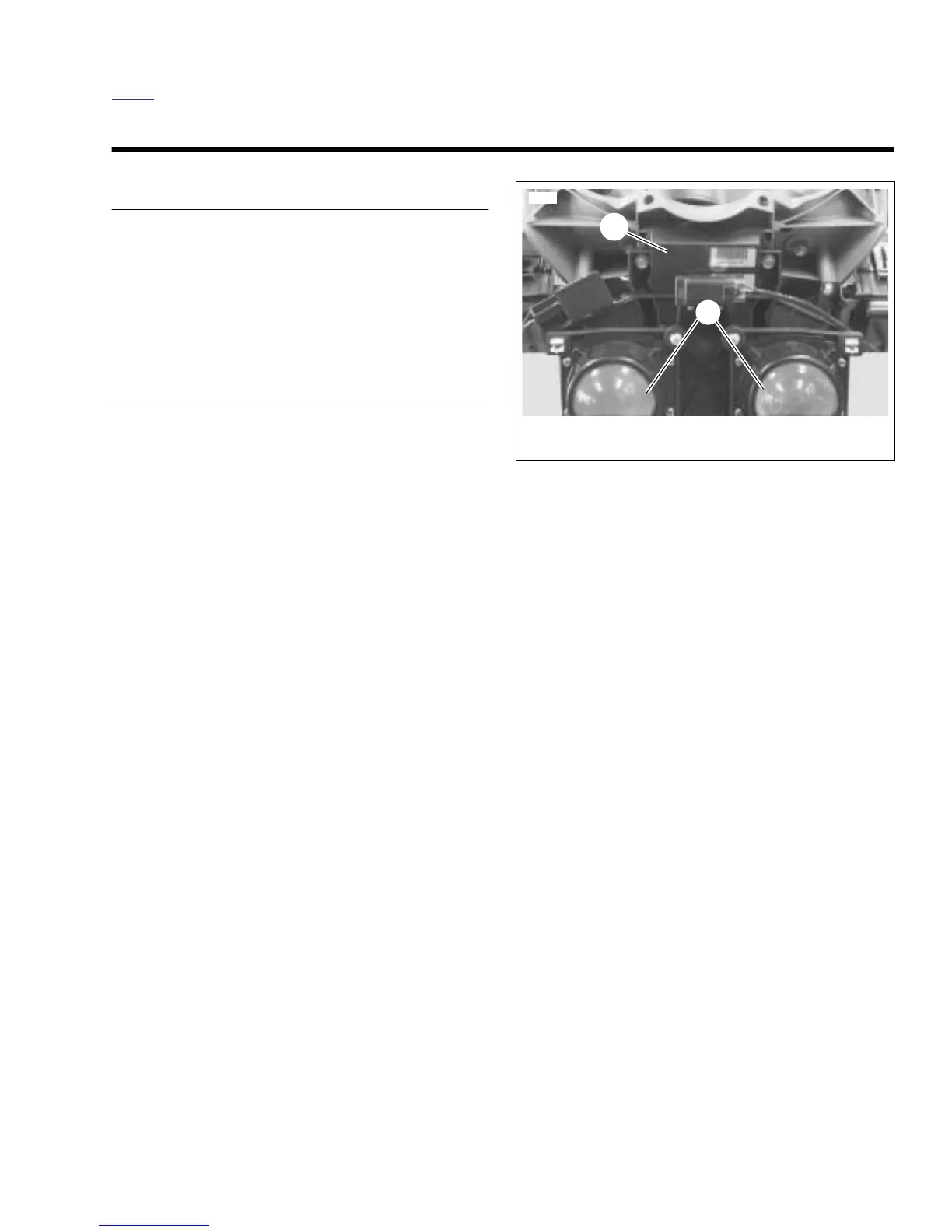
3. Disconnect ECM black connector [10] and gray connec-
tor [11].
INSTALLATION
1. Attach ECM connectors [10] and [11].
2. Locate ECM between fairing and headlight bracket.
3. Install headlight bracket. See 2.25 HEADLIGHT ASSEM-
BLY AND SUPPORT BRACKET.
4. Install front fairing. See 2.37 FRONT FAIRING, WIND-
SHIELD, AND MIRRORS.
5. Re calibrate throttle position sensor using DIGITAL
TECHNICIAN (Part No. HD-44750).
Figure 4-63. ECM
 Loading...


