7-48 2005 Buell Firebolt: Electrical
HOME
TURN SIGNAL FLASHER 7.15
REMOVAL
NOTE
The turn signal flasher is not repairable. Replace flasher upon
failure.
1. Remove front fairing. See 2.37 FRONT FAIRING, WIND-
SHIELD, AND MIRRORS.
2. Remove fastener securing turn signal flasher to head-
light support bracket.
3. Detach 3-place connector [30] from flasher body.
INSTALLATION
1. See Figure 7-53. Attach 3-place connector [30] to
flasher.
2. Install turn signal to headlight support bracket. Tighten
fastener to 30-40 in-lbs (3.4-4.5 Nm).
3. Install front fairing. See 2.37 FRONT FAIRING, WIND-
SHIELD, AND MIRRORS.
1WARNING1WARNING
Be sure that all lights and switches operate properly
before operating motorcycle. Low visibility of rider can
result in death or serious injury. (00316a)
4. Check turn signals for proper operation. If operation fails,
reread procedure and verify that all steps were per-
formed.
a. Turn ignition key switch to IGN.
b. See Figure 7-54. Activate left turn signals using
switch on left handlebar. Front and rear left turn sig-
nals must flash.
c. Activate right turn signals using switch on left han-
dlebar. Front and rear right turn signals must flash.
d. Turn ignition key switch to OFF.
Figure 7-53. Turn Signal Flasher
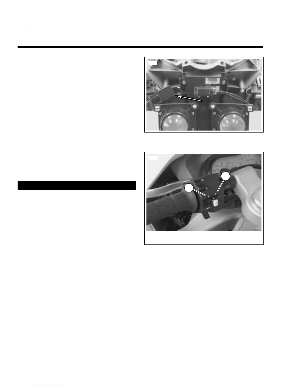
Figure 7-54. Turn Signal Controls
8428
8370
2
1. Left turn signal
2. Right turn signal
1