2-92 2005 Buell Firebolt: Chassis
HOME
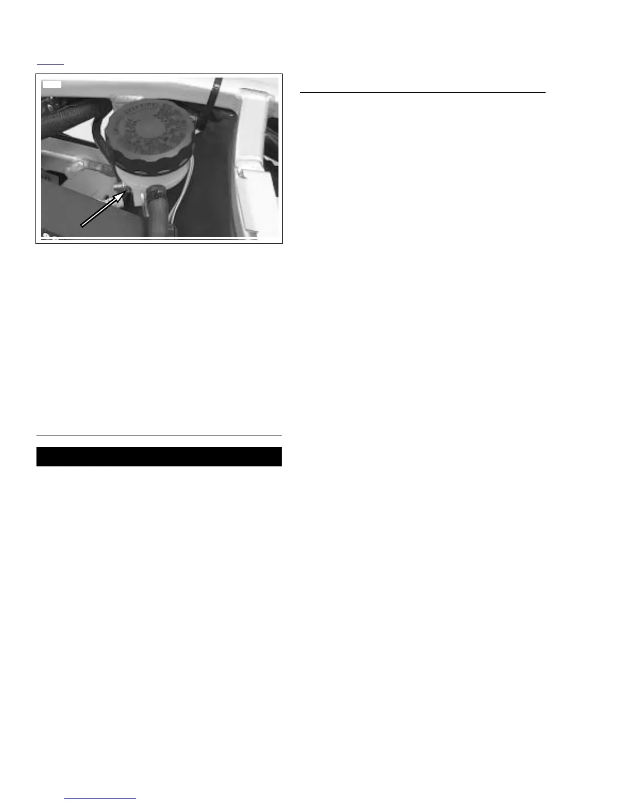
17. See Figure 2-123. Remove rear brake reservoir clamp
nut.
18. Disconnect fuel pump connection and remove case from
subframe tail assembly. See 4.39 FUEL PUMP/EARLY
MODEL YEAR.
19. Remove shock reservoir fasteners and feed the reservoir
out of subframe tail assembly. See 2.22 REAR SHOCK
ABSORBER.
20. See Figure 2-120. Remove subframe tail assembly fas-
teners (8) and remove subframe tail assembly (7) from
frame.
CLEANING
CAUTION
Do not use wheel care products or other compounds
developed specifically for cleaning and polishing pow-
dercoat. These cleaners could potentially damage the tail
section finish.
The cast aluminum tail section has a black powdercoat.
Because the surface is not bare polished aluminum, it must
be cleaned using only mild soap and warm water. After wash-
ing, always dry the surface using a clean, soft cloth.
ASSEMBLY
1. Install subframe tail assembly (7) to frame and tighten
fasteners (8) to 21-23 ft-lbs (28-31 Nm) using LOCTITE
272.
2. Connect fuel pump connection and install connection
case onto subframe tail assembly. See 4.39 FUEL
PUMP/EARLY MODEL YEAR.
3. See Figure 2-122. Feed rear brake light connector (5)
into subframe tail assembly and connect.
4. Install main fuse case (3) onto subframe tail assembly.
5. Install main battery ground (1) and ground to wire har-
ness (2) to subframe tail assembly. Tightening fastener to
72-96 in-lbs (8-11 Nm).
6. See Figure 2-121. Feed the rear shock reservoir (4)
through second subframe tail assembly support.
7. Install rear shock reservoir into shock reservoir clamp
and install clamp on to subframe tail assembly. Do not
tighten. See 2.22 REAR SHOCK ABSORBER.
8. Check rear shock reservoir suspension screw alignment
with upper body work.
a. Install upper body work without tightening any fas-
teners.
b. Move the rear shock canister in position to see the
suspension screw through the upper body work.
c. Remove upper body work and tighten rear shock
reservoir clamp to 120-144 in-lbs (14-16 Nm).
9. See Figure 2-121. Feed fuel vent hose (1) through tail
section, keeping the hose on top of rear shock reservoir
hose. See D.1 HOSE AND WIRE ROUTING for hose and
wire routing.
10. Install cable strap (3) holding shock reservoir hose, wire
harness and fuel vent hose to subframe tail assembly.
11. See Figure 2-123. Feed rear brake reservoir hose under-
neath subframe tail assembly and install rear brake res-
ervoir tightening fastener to 48-72 in-lbs (5.4-8.1 Nm).
12. See Figure 2-122. Install cable strap holding brake light
connector and rear reservoir hose.
Figure 2-123. Remote Reservoir Clamp Nut
8359
 Loading...


