3-64 2005 Buell Firebolt: Engine
HOME
CAUTION
Handle the piston with extreme care. The alloy used in
these pistons is very hard. Any scratches, gouges or
other marks in the piston could score the cylinder during
engine operation and cause engine damage.
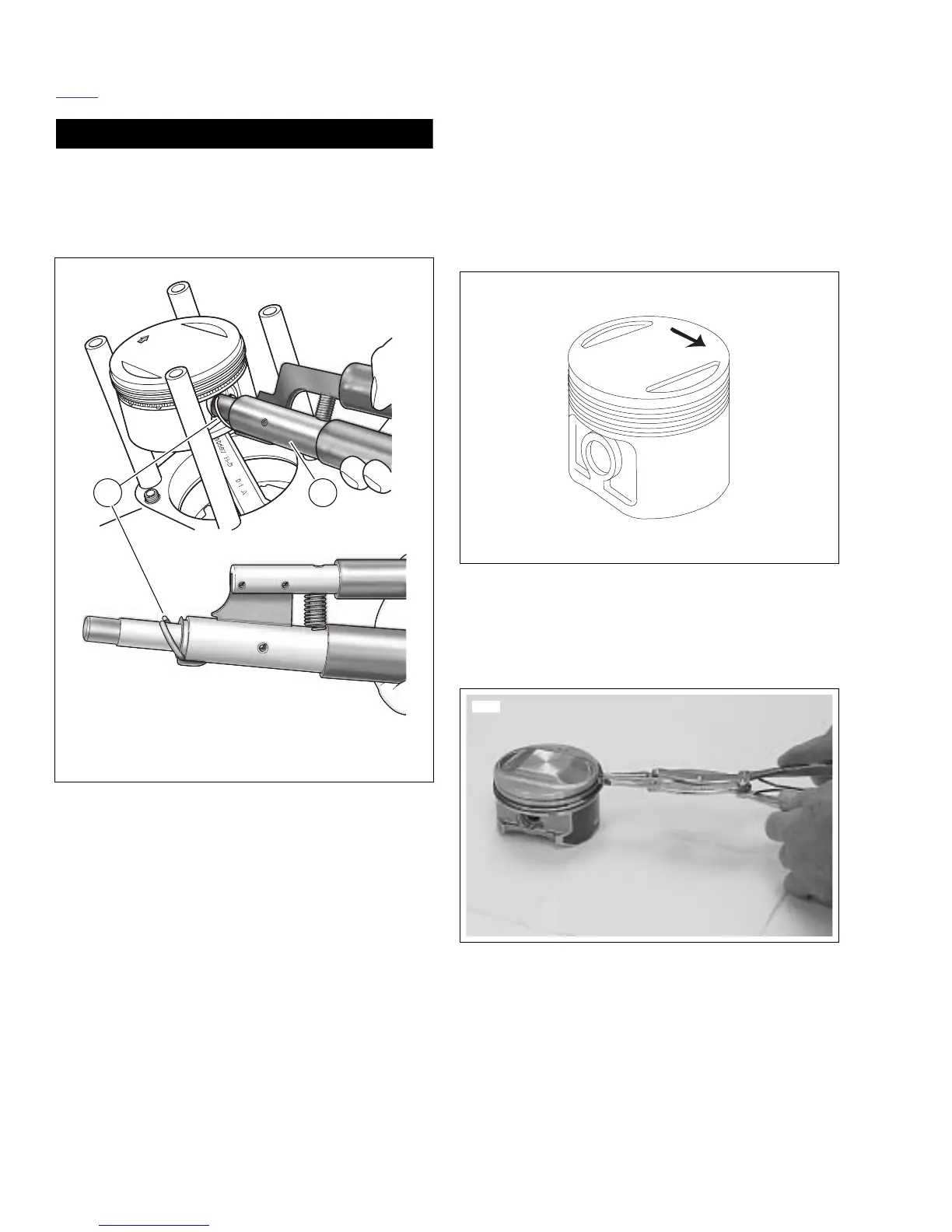
8. See Figure 3-90. Remove the piston pin circlip as fol-
lows:
a. Insert the PISTON PIN CIRCLIP REMOVER/
INSTALLER (Part No. HD-34623C) into the piston
pin bore until claw on tool is positioned in slot of pis-
ton (directly under circlip).
b. Squeeze the handles of the tool together and pull
from bore. In the event that the circlip should fly out,
hold a shop towel over the bore during removal.
Remove circlip from claw and discard.
NOTES
● It is not necessary to remove both piston pin circlips dur-
ing piston removal. Leave the second circlip in the pin
bore.
● Since the piston pin is a loose fit in the piston, the pin will
easily slide out. The pin has tapered ends to help seat
the round retaining rings.
NOTE
See Figure 3-91. The arrow at the top of pistons must always
point toward the front of the engine.
9. See Figure 3-92. To remove piston rings spread outward
until they clear grooves in piston and lift off.
Figure 3-90. Removing Piston Pin Circlip
b1002x3x
b1001x3x
1. Piston pin retaining ring
2. Piston pin retaining ring installer
(Part No. HD-34623C)
1 2
Figure 3-91. Piston Pin and Piston Identification
Figure 3-92. Removing Piston Rings
b0057c3x
8638









 To Next Page