2005 Buell Firebolt: Maintenance 1-23
HOME
Rear Pad Removal
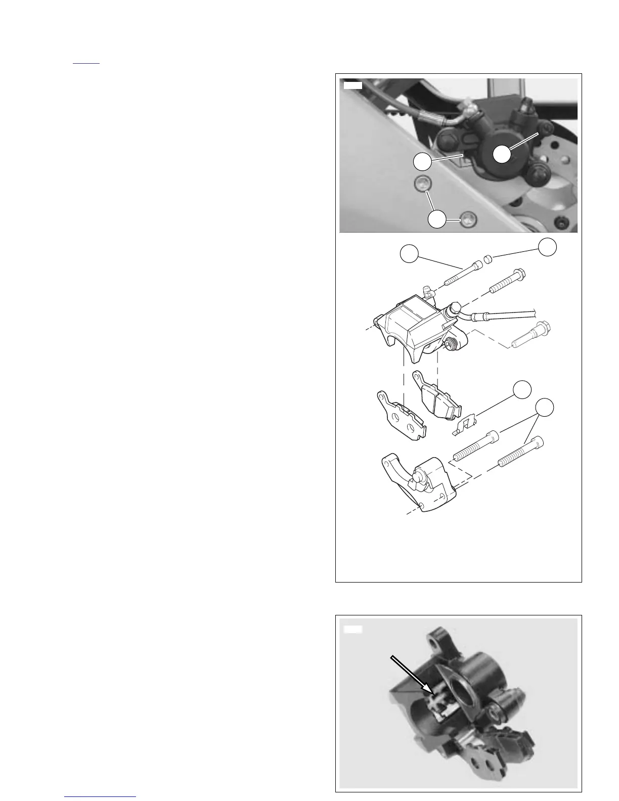
1. See Figure 1-16. Remove rear caliper pin plug (3) and
loosen pin (4).
2. Remove fastener securing p-clamp, wire form and brake
line assembly to swingarm.
3. Remove two mounting fasteners (1) securing brake cali-
per and carrier assembly to swingarm.
4. Lift caliper and carrier assembly up and off of rotor.
5. Remove hanger pin (4).
6. Remove inner and outer pads, being careful not to dis-
lodge pad spring.
Rear Pad Installation
1. See Figure 1-16. Check that retainer (2) is present.
2. See Figure 1-17. Check that pad spring is present.
Should pad spring become dislodged, install with widest
area of spring towards piston side of caliper.
3. Push piston in with suitable tool such as a clean paint
scraper until fully seated in bore.
4. Install new inner and outer brake pads
5. See Figure 1-16. Install hanger pin (4) making sure pin
engages hole on both pads.
6. Install brake caliper and carrier assembly over rotor.
7. Install two mounting fasteners (1) through swingarm into
carrier and tighten to 35-37 ft-lbs (48-50 Nm).
8. Apply LOCTITE 272 and tighten hanger pin to 11-14 ft-
lbs (14.9-18.9 Nm).
9. Install pin plug (3). Tighten plug to 18-25 in-lbs (2-
3 Nm).
10. Install fastener securing p-clamp, wire form and brake
line assembly to swingarm and tighten to 36-60 in-lbs
(4.1-6.8 Nm).
NOTE
Avoid making hard stops for the first 100 miles (160 km) to
allow new brake pads to “wear in” properly with the rotor.
Figure 1-16. Rear Brake Caliper
Figure 1-17. Rear Brake Pad Spring
 Loading...


