2005 Buell Firebolt: Fuel System 4-39
HOME
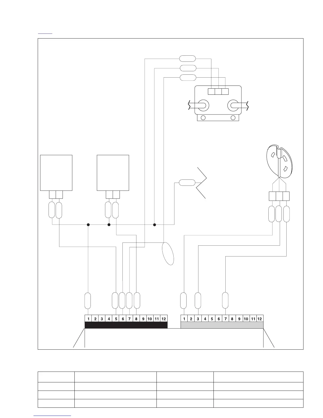
Figure 4-30. Ignition Coil Circuit
Table 4-16. Wire Harness Connectors in Figure 4-30.
NO. DESCRIPTION TYPE LOCATION
[10] ECM (black) 12-place Deutsch in fairing
[22] right hand controls 4-place Multilock beneath right side of fairing
[83] ignition coil 3-place Packard beneath airbox base
Front
Injector
[84]
Ignition Coil [83]
W/Y
GN/W
BK/W
R/W
Electronic Control Module (ECM)
Connector [10] Connector [11]
GY
Cam Position
Sensor [14]
A
GN/W
Y/BE
GY
BE/O
BK/W
B
C
A
A
3
12
B
B
To Rear
Cylinder
To Front
Cylinder
W/Y
GN/GY
R/W
Rear
Injector
[85]
GY
To Ignition
Relay
Y/BE
GY
BE/O
GY
GN/GY
Dyno Loop
b1071x4x








 To Next Page