4-78 2005 Buell Firebolt: Fuel System
HOME
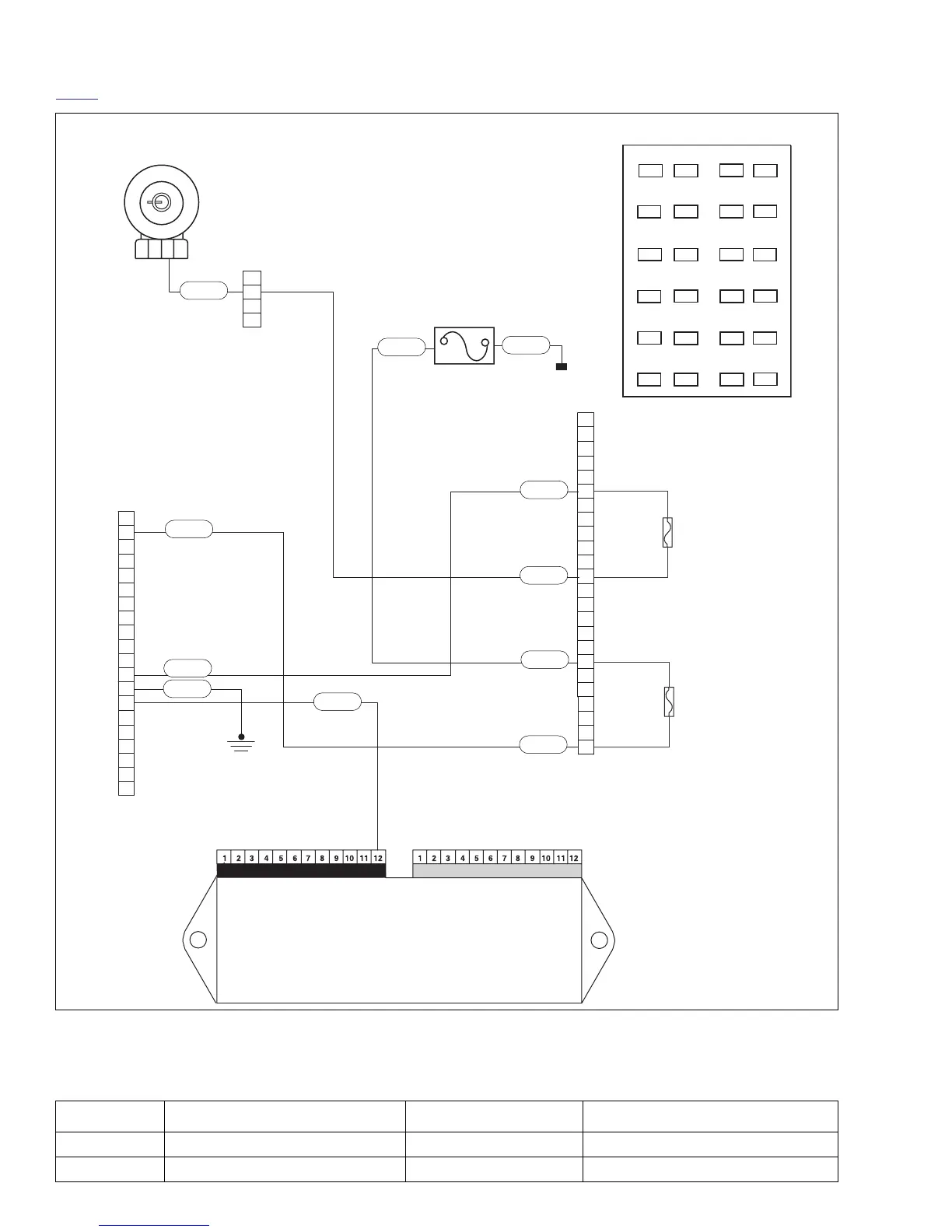
Figure 4-55. Tachometer Circuit
1
2
3
4
1
3
4
5
6
7
8
9
10
11
12
13
14
15
16
17
18
19
20
21
22
23
24
2
1
2
3
4
5
6
7
8
9
10
11
12
13
14
15
16
17
18
19
20
19
20
21
22
23
24
13
14
15
16
17
18
1
2
3
4
5
6
7
8
9
10
11
12
11
Spare
Diode
Bk/Hn/Mflr
Fan
IGN
Acces.
Key Sw
Lights
ECM
Spare
Empty
Empty
R/GY
O/W
BK
Ignition
Switch
[33]
To battery
Electronic Control Module
(ECM)
Connector [10]
Connector [11]
Instrument
Module [39]
R
R/Y
R/GY
O/W
R
R
R
Main Fuse
Fuse Block
R/GY
Accessory
Fuse
Key Switch
Fuse
b1084c4x
PK
Top View
Table 4-28. Wire Harness Connectors in Figure 4-55.
NO. DESCRIPTION TYPE LOCATION
[10] ECM (black) 12-place Deutsch in fairing
[39] instrument module 20-place Multilock in fairing