2005 Buell Firebolt: Drive/Transmission 6-27
HOME
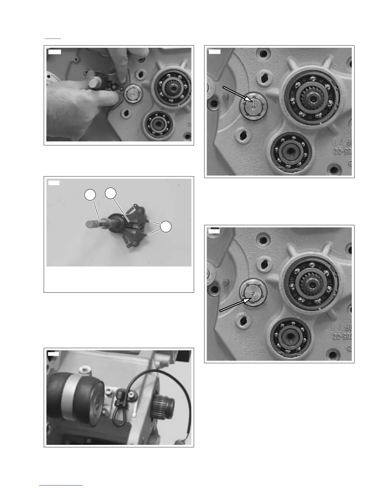
10. See Figure 6-49. Remove shifter shaft assembly.
11. See Figure 6-50. Depress ratchet arms in order to clear
the shifter drum and remove shifter shaft assembly from
left crankcase half.
12. Remove starter. See 5.7 STARTER.
13. See Figure 6-51. Remove rear isolator assembly by
removing the forward two fasteners first and then the two
rear fasteners (re-install with
new
fasteners).
14. See Figure 6-52. Scribe a line on the end of the shifter
drum at the 12 o’clock position for later reference.
15. See Figure 6-53. Place transmission in 4th gear. The
scribed line should now be at the 6 o’clock position.
NOTE
Transmission can be easily shifted by rotating the mainshaft
and shifter drum at the same time by hand.
Figure 6-49. Removing Shifter Shaft Assembly
Figure 6-50. Shifter Shaft Assembly
Figure 6-51. Rear Isolator Assembly
8617
1. Shifter shaft
2. Ratchet arms
3. Return spring
2
3
1
8626
8723a
Figure 6-52. Scribed Line on Shifter Drum at 12 o’clock
(Transmission in Neutral)
Figure 6-53. Scribed Line on Shifter Drum at 6 O’clock
(Transmission in 4th Gear)
 Loading...


