2005 Buell Firebolt: Drive/Transmission 6-37
HOME
COUNTERSHAFT ASSEMBLY
11WARNING1WARNING
Wear safety glasses or goggles when removing or install-
ing retaining rings. Retaining rings can slip from the pli-
ers and could be propelled with enough force to cause
serious eye injury. (00312a)
CAUTION
During assembly, the split bearings and the internal
bores of the gears must be lubricated with SPORT-
TRANS FLUID prior to assembly. Leaving these parts dry
could accelerate wear at start-up.
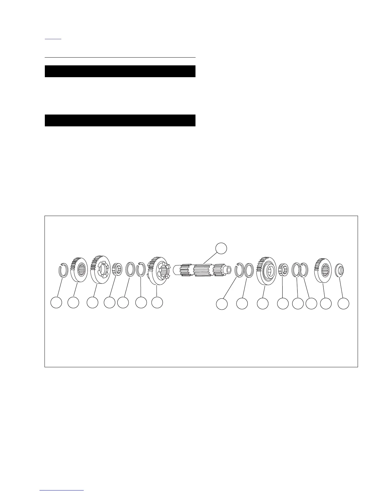
1. See Figure 6-69. Install
new
retaining ring (1) and thrust
washer (2) onto countershaft in the second ring groove
from the end with internal threads.
2. Install split bearing (4) onto countershaft.
3. Locate countershaft 1st gear (3), identified by one radial
groove at one side, and slide gear onto shaft. Position
gear over bearing (4).
4. Install thrust washer (5) and
new
retaining ring (6) next
to countershaft 1st gear (3).
5. Install countershaft 3rd gear (7) on countershaft with fork
groove facing away from countershaft 1st gear (3).
6. Install
new
retaining ring (8) on countershaft. Position
new
retaining ring in the second ring groove from the
end. Install thrust washer (9) next to retaining ring (8).
Install split bearing (10) in seat next to washer (9).
5. Install countershaft 2nd gear (11) with the locking dogs
facing countershaft 3rd gear (7).
6. Install countershaft 5th gear (12) on countershaft.
7. Install
new
retaining ring (13) on countershaft.
8. Locate countershaft 4th gear (14). This flat, shoulder less
gear is splined and has a single radial groove at one
side. Position gear next to retaining ring (6) on counter-
shaft. Place beveled spacer (15) over end of shaft with
beveled side away from countershaft 4th gear (14).
NOTE
At this point both mainshaft and countershaft sub-assemblies
are ready to be pressed into the left crankcase half.
Figure 6-69. Transmission Countershaft Assembly/Reassembly
54 632
1
7891013 12 11
1. Retaining ring
2. Thrust washer
3. Countershaft 1st
4. Split bearing
5. Thrust washer
6. Retaining ring
7. Countershaft 3rd
8. Retaining ring
9. Thrust washer
10. Split bearing
11. Countershaft 2nd
12. Countershaft 5th
13. Retaining ring
14. Countershaft 4th
15. Beveled spacer
16. Countershaft
b1020x6x
14 15
Left Crankcase
16














 To Next Page