2005 Buell Firebolt: Drive/Transmission 6-45
HOME
SHIFTER FORKS AND DRUM
ASSEMBLY
NOTES
●
See Figure 6-85. Shifter fork design allows for one com-
mon part number for all three shifter forks. As the trans-
mission runs, each shifter fork develops a certain wear
pattern with its mating parts. For this reason, it is impor-
tant that each shifter fork be reinstalled in its original
location.
●
Always lubricate the shaft bore in each shifting fork with
Sport Transmission Lube before assembly.
1. Place the 4th gear shifter fork on the appropriate main-
shaft sliding gear.
2. Install the shifter drum into the left case half with the pre-
viously scribed line at the 6 o’clock position. This will
place the shifter drum in the 4th gear position.
3. See Figure 6-86. Place the 3rd and 5th gear shifter fork
on the appropriate mainshaft sliding gear and install the
shifter fork shaft through the two installed shifter forks
and into the left case half.
4. Install the 1st and 2nd gear shifter fork on the appropri-
ate countershaft sliding gear and install the remaining
shifter fork shaft through the last installed shifter fork and
into the left case half.
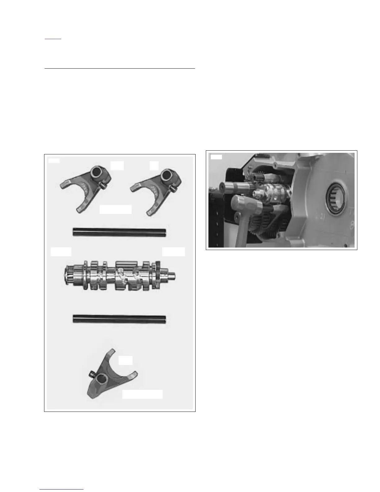
NOTE
See Figure 6-86. Install shifter fork shafts in the left case half
by lightly tapping on the end with a brass hammer until
seated in bore.
Figure 6-85. Shifter Forks, Drum and Shafts
8616
Countershaft
Mainshaft
Left Right
3-5 4
1-2
Figure 6-86. Installing Shift Fork Shafts