2005 Buell Firebolt: Drive/Transmission 6-47
HOME
INSTALLING RIGHT CRANKCASE
1. See Figure 6-88. Install the flywheel assembly into the
left crankcase half using CRANKSHAFT GUIDE TOOL
Part No. HD-42326.
NOTE
The Gear Detent Assembly Aid is used to move the gear
detent lever clear of the shifter drum for assembly purposes.
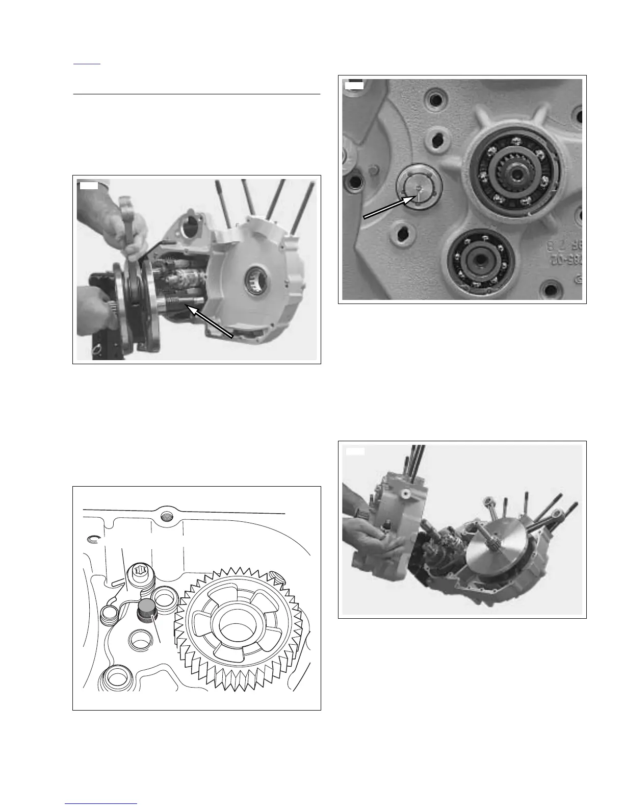
2. See Figure 6-89. Retract detent assembly in right case
half and install GEAR DETENT ASSEMBLY AID (Part
No. B-45520) until it has bottomed in right case half.
3. See Figure 6-90. Place Transmission in the 4th gear
position. The scribed line on the shifting drum should be
at 6 o’clock.
4. Lubricate both main drive gear needle bearing assem-
blies and the mating surface of the mainshaft with HAR-
LEY-DAVIDSON SPECIAL PURPOSE GREASE (Part
No. 99857-97).
5. See Figure 6-91. Assemble crankcase halves together.
a. Apply a thin coat of DOW CORNING SILASTIC
#732 clear sealant to crankcase joint faces
b. Apply several drops of LOCTITE 262 (red) to last
few threads.
c. See Figure 6-87. Tighten 5/16-in. fasteners to 15-19
ft-lbs (20.3-25 Nm).
Figure 6-88. Installing Flywheel Assembly Using Crank-
shaft Guide Tool (Part No. HD-42326)
Figure 6-89. Gear Detent Assembly Aid
(Part No. B-45520)
8622
b1067x6x
Detent Assembly
Tool
Figure 6-90. Scribed Line on Shifter Drum at 6 O’clock
(Transmission in 4th Gear)
Figure 6-91. Crankcase Halves