7-6 2005 Buell Firebolt: Electrical
HOME
REMOVAL
1. Remove seat. See 2.38 SEAT.
1WARNING1WARNING
To prevent accidental vehicle start-up, which could
cause death or serious injury, disconnect negative (-)
battery cable before proceeding. (00048a)
2. Disconnect negative battery cable.
3. See Figure 7-6. Cut cable strap (2) holding ignition
switch, fuse block and right handlebar switch wires.
4. Disconnect ignition switch connector [33] (3).
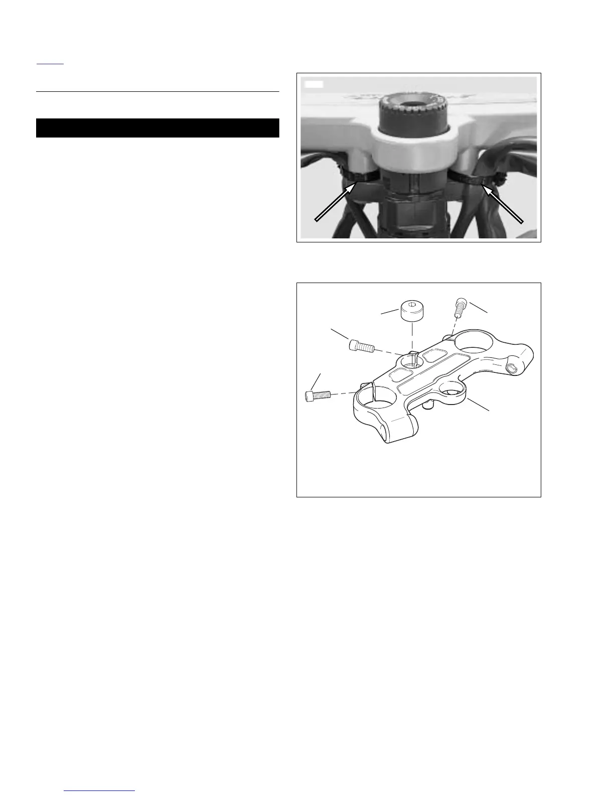
5. See Figure 7-3. Remove cable straps attached to the
upper fork clamp.
6. Remove airbox cover. See 2.34 INTAKE COVER
ASSEMBLY.
7. See Figure 7-4. Remove steering stem pinch fastener
(2).
8. Remove upper fork clamp pinch fasteners (1).
9. See Figure 7-4. Hold or brace the lower fork clamp and
remove steering stem cap (3).
10. Remove the upper fork clamp (4) from forks.
11. See Figure 7-5. Use Snap-on Tamper-Resistant T45 Torx
driver, Part No FTXR45E to remove ignition switch fas-
teners (3) securing ignition switch (4) to upper fork
clamp. Slide ignition switch out of upper fork clamp.
Figure 7-3. Cable Straps On Upper Fork Clamp
Figure 7-4. Upper Fork Clamp
8454
1. Upper fork clamp pinch fastener (2)
2. Stem pinch fastener
3. Stem cap fastener
4. Upper fork clamp
1
1
2
3
4
b1109x7x
 Loading...


