EasyManua.ls Logo

Buell 2005 FIREBOLT - Page 536

Buell 2005 FIREBOLT
621 pages
Print Icon
To Next Page IconTo Next Page
To Previous Page IconTo Previous Page
Loading...
2005 Buell Firebolt: Electrical 7-51
HOME
VEHICLE SPEED SENSOR 7.17
REMOVAL
1. See Figure 7-57. Remove fastener (1) to detach vehicle
speed sensor (2) from crankcase.
2. Remove cable strap (4).
3. Disconnect 3-place Deutsch connector [65] under
sprocket cover. See 7.24 INTERACTIVE EXHAUST
HARNESS(XB12 MODELS).
INSTALLATION
1. See Figure 7-57. Lube O-ring with engine oil and install
fastener (1) to attach vehicle speed sensor (2) to crank-
case.
2. Connect vehicle speed sensor connector [65] to wiring
harness. See 7.24 INTERACTIVE EXHAUST HAR-
NESS(XB12 MODELS).
3. Install cable strap (4).
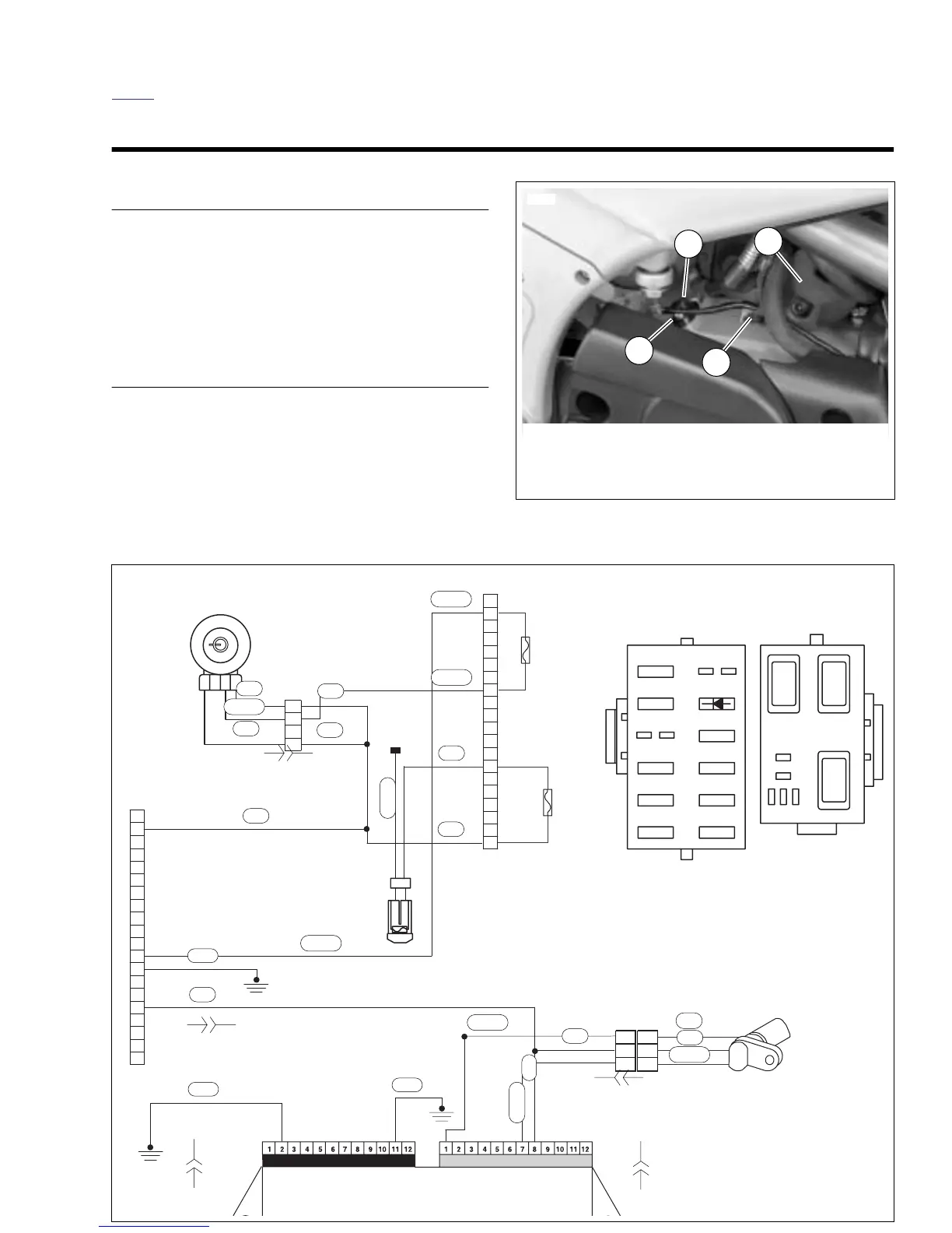
Figure 7-57. Speedometer Sensor
1
8741a
2
3
4
1. Fastener
2. Vehicle speed sensor
3. Starter
4. Cable strap
Figure 7-58. Vehicle Speed Sensor Wiring
1
2
3
4
2
1
[5A]
1
2
3
4
5
6
7
8
9
10
11
12
13
14
15
16
17
18
19
20
5
6
8
9
10
11
12
13
14
15
16
17
18
19
20
21
22
23
24
7
RELAY
CENTER
ISO
ISOISO
KEY SW.
IGNITION
START
Spare
Diode
Bk/Hn/Mflr
Fan
IGN
15A
15A
10A
10A
10A
10A
15A
15A
10A
Acces.
Key Sw
Lights
ECM
Spare
FUSE BLOCK
J-FUSE ASSY
b1104d7x
Vehicle Speed
Sensor
Vehicle Speed Sensor
Connector
Electronic Control Module
(ECM)
Connector
Connector
Accessory
Fuse
Key Switch
Fuse
To battery
Ignition
Switch
R/GY
Instrument Module
R
R
R
R
R
R
R/Y
O/W
R
O/W
BK
W
W
BK
BK
BK/W
W
W
R
BK/W
R/W
R/GY
AA
BB
C
C
[39A] [39B]
[10B]
[10A]
[65B][65A]
[11B]
[11B]
[33B]
[33A]

Table of Contents