7-54 2005 Buell Firebolt: Electrical
HOME
INSTALLATION
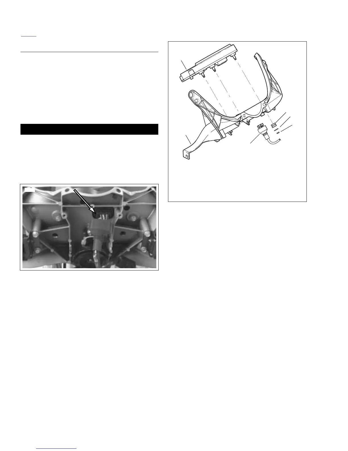
1. See Figure 7-64. Place instrument module (2) into posi-
tion in headlight support bracket (1).
2. Install washers (4) and fasteners (5). Tighten fasteners to
12-36 in-lbs (1.4-4.0 Nm).
3. See Figure 7-63. Connect instrument module connector
[39].
4. Install headlight support bracket. See 2.25 HEADLIGHT
ASSEMBLY AND SUPPORT BRACKET.
5. Install negative battery cable.
1WARNING1WARNING
After installing seat, pull upward on front of seat to be
sure it is in locked position. While riding, a loose seat can
shift causing loss of control, which could result in death
or serious injury. (00070a)
Install seat. See 2.38 SEAT.
Figure 7-63. Instrument Module Connector [39]
8426
Figure 7-64. Instrument Module
b1009x7x
2
1
6
3
4
5
1. Headlight support bracket
2. Instrument module
3. Grommet (3)
4. Washer (3)
5. Fastener (3)
6. Instrument module connector [39]
 Loading...


