7-72 2005 Buell Firebolt: Electrical
HOME
NOTE
In next step, be sure loops in cam position sensor and neutral
switch wiring are intact.
7. Use cable strap (5) to secure cam position sensor (1),
cam position sensor wiring (3), neutral switch connector
(4) and neutral switch connector wiring (6).
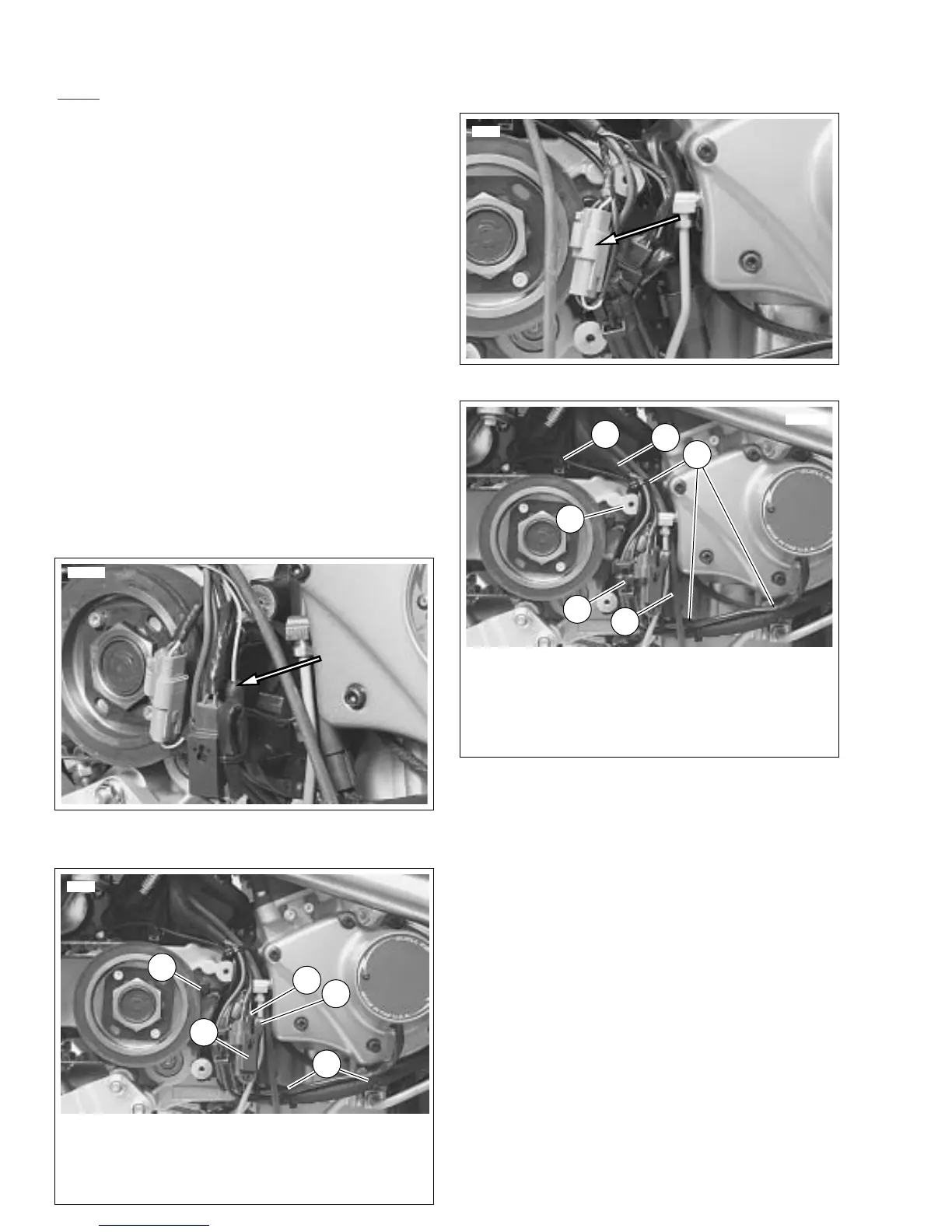
8. See Figure 7-91. Connect vehicle speed sensor connec-
tor.
NOTE
See Figure 7-92. In next step, be sure main harness (4) is
routed around sprocket cover boss (2).
9. See Figure 7-92. Connect voltage regulator connector
[77] (1). Be sure connector latch faces inward and volt-
age regulator wires are positioned behind other wires in
harness at sprocket cover boss (2).
10. Install cable strap (3) securing vehicle speed sensor wir-
ing to starter connector [128] wiring.
11. Install cable strap (5) securing main harness wiring.
12. Install cable strap (6) securing stator, cam position sen-
sor and oil pressure switch wiring.
13. Add cable strap (7) to secure cam position sensor and
voltage regulator wiring.
Figure 7-89. Neutral Switch Connector [131]
Figure 7-90. Neutral Switch Wiring
10540
10549
1. Cam position sensor connector [14]
2. Neutral switch location
3. Cam position sensor wiring
4. Neutral switch connector [131]
5. Cable strap
2
1
4
3
5
Figure 7-91. Vehicle Speed Sensor Connector [65]
Figure 7-92. Assembled Wiring
8717b
10549
1. Voltage regulator connector [77]
2. Sprocket cover boss
3. Cable strap
4. Main harness
5. Cable strap
6. Interactive exhaust cable
3
1
2
4
5
6



 To Next Page